
 English
 Español
 Français
 简体中文
简体中文ADD: No.85 Jiuyuan Road, Economic Development Zone, Gaoyou city ,Yangzhou city ,225600 Jiangsu Province, China.
MERCEDES-BENZC-CLASS (W203) (2000/05 - 2007/08)MERCEDES-BENZC-CLASS Coupe (CL203) (2001/03 - 2011/06...
See DetailsContent
A thermistor is the better choice when you need fast response, low cost, and high sensitivity across a narrow temperature band, while an RTD, short for Resistance Temperature Detector, is the better choice when you need long term stability, wide temperature range, and repeatable accuracy across years of continuous operation. Both belong to the broader family of Thermal Resistance Temperature Sensor devices, meaning their electrical resistance changes predictably with temperature, but the way that resistance changes and how reliably it holds over time is where the two technologies split apart.
If your application involves a compact space, a budget under a few dollars per unit, and a temperature window roughly between negative 50 and 150 degrees Celsius, a thermistor typically wins. If your application involves industrial process control, laboratory calibration, or continuous monitoring above 150 degrees Celsius, an RTD typically wins. The remainder of this guide breaks down exactly why, with the underlying physics, comparative data tables, wiring differences, and selection guidance you can apply directly to a design decision.
Both devices are classified as a Thermal Resistance Temperature Sensor because both rely on a predictable relationship between electrical resistance and temperature. The construction and the material behind that relationship, however, could not be more different.
| Attribute | Thermistor | RTD |
|---|---|---|
| Material | Sintered ceramic metal oxides such as manganese, nickel, or cobalt oxide | Pure metal wire or film, almost always platinum |
| Resistance behavior | Highly nonlinear, exponential curve | Nearly linear curve across most of the range |
| Typical base resistance | 2,000 to 10,000 ohms at 25 degrees Celsius | 100 or 1,000 ohms at 0 degrees Celsius |
| Common type designation | NTC (negative temperature coefficient) or PTC (positive temperature coefficient) | PT100 or PT1000 platinum element |
Most commercially available thermistors are NTC types, meaning resistance drops sharply as temperature rises. RTDs move in the opposite direction, resistance rises steadily and almost linearly as temperature rises, which is one reason RTDs are easier to characterize mathematically across a broad span.
Thermistor manufacturers typically supply resistance data fitted to the Steinhart-Hart equation, a three-coefficient formula that models the steep, curved resistance response with very high precision inside a defined window. Because the curve is so steep, a thermistor can detect a fraction of a degree change with far more resolution than an RTD at the same excitation current, which is exactly why thermistors dominate applications like body temperature probes, battery pack monitoring, and HVAC thermostats.
RTD behavior is instead modeled with the Callendar-Van Dusen equation, which produces a much flatter, more linear curve. The tradeoff is lower sensitivity per degree, meaning the signal conditioning circuit has to amplify a smaller change, but the payoff is a curve that behaves almost identically from one production batch to another. This batch to batch consistency is the single biggest reason RTDs are preferred wherever long-term calibration stability outweighs raw sensitivity.
Accuracy numbers are frequently misunderstood because a sensor can be highly accurate on day one and drift significantly after a year of thermal cycling. This is where the two technologies diverge most sharply.
| Metric | Thermistor | RTD (Platinum PT100) |
|---|---|---|
| Initial accuracy at 25 degrees Celsius | 0.1 to 0.2 degrees Celsius on premium grades | 0.1 to 0.3 degrees Celsius depending on tolerance grade |
| Accuracy at the edge of the rated range | Degrades quickly, often 1 to 2 degrees Celsius | Remains within 0.5 degrees Celsius across most of the span |
| Long term drift per year of continuous use | Can exceed 0.2 degrees Celsius per year in harsh cycling | Typically below 0.05 degrees Celsius per year |
| Repeatability across production batches | Moderate, curve fitting required per batch | High, platinum behaves almost identically batch to batch |
These figures are drawn from widely published sensor engineering reference data rather than a single manufacturer, so treat them as representative ranges rather than guarantees for any specific part number. The core takeaway is that thermistors win on precision near their center point, while RTDs win on maintaining that precision over years of service.
Range is often the deciding factor before accuracy even enters the conversation, because a sensor that cannot physically survive the application temperature is disqualified immediately.
For cryogenic testing near negative 200 degrees Celsius or furnace monitoring above 500 degrees Celsius, RTDs are effectively the only practical option among the two. For consumer electronics and medical devices that never leave a narrow band around room temperature or body temperature, a thermistor is almost always the more economical and more sensitive choice.
Response time depends heavily on thermal mass, and thermal mass depends on physical size, so this comparison is closely tied to packaging.
If your process requires catching rapid temperature spikes, such as motor winding protection or fast thermal cycling tests, the smaller thermal mass of a thermistor generally gives it the edge in raw speed.
Wiring complexity is another practical difference that shows up in installation labor and cabling cost, especially on long cable runs where wire resistance itself becomes a measurement error.
| Configuration | Used With | Purpose |
|---|---|---|
| 2-wire | Thermistors and low-cost RTDs | Simplest wiring, but lead wire resistance adds direct error, only suitable for short cable runs |
| 3-wire | Industrial RTDs | Cancels out most lead wire resistance error, the standard configuration for process instrumentation |
| 4-wire | Laboratory and calibration grade RTDs | Removes lead wire resistance almost entirely, delivering the highest achievable accuracy |
Thermistors are almost always wired with a simple 2-wire configuration because their base resistance is thousands of ohms, making a few ohms of lead wire resistance statistically insignificant. RTDs sit at only 100 or 1,000 ohms, so the same few ohms of lead wire resistance becomes a meaningful error source, which is exactly why 3-wire and 4-wire configurations exist specifically for RTD installations.
Purchase price tells only part of the story. Installation labor, signal conditioning electronics, and expected service life all factor into the real total cost of ownership.
For high-volume consumer products where the sensor is replaced along with the whole device, thermistors almost always deliver the lower total cost. For fixed industrial installations expected to run for a decade or more without replacement, the higher initial cost of an RTD is frequently justified by reduced downtime and recalibration.
| Industry | Thermistor Use Case | RTD Use Case |
|---|---|---|
| Consumer electronics | Battery pack temperature monitoring, laptop thermal management | Rarely used, cost and size are prohibitive |
| Medical devices | Body temperature probes, infusion pump monitoring | High precision lab diagnostic equipment |
| HVAC and appliances | Thermostats, refrigerator and freezer sensors | Rarely used except in premium building automation systems |
| Industrial process control | Rarely used above moderate temperatures | Furnace monitoring, chemical processing, food and beverage pasteurization lines |
| Automotive | Cabin air temperature, coolant temperature in many platforms | Exhaust gas temperature, engine bay high temperature zones |
Work through these four questions in order and the correct sensor family usually becomes obvious well before you reach the last one.
A common misconception is treating this as an either-or decision at the company level. Many manufacturers use thermistors for fast, cheap, high-volume monitoring points and RTDs for the handful of critical, high-precision measurement points within the same system, combining both technologies inside a single Thermal Resistance Temperature Sensor network.
RTDs generally outperform thermistors in mechanical durability because the sensing element is a stable metal rather than a ceramic that can develop microcracks under repeated thermal shock. Wire wound RTDs in particular are known for remaining within their original calibration tolerance after tens of thousands of thermal cycles, while thermistors exposed to the same cycling regime are more likely to show measurable drift within a few years of continuous industrial use.
Neither sensor type requires routine servicing in normal operation, but periodic verification against a known reference point is good practice for any critical measurement loop, particularly for RTDs used in regulated process monitoring where drift of even a fraction of a degree can affect product quality outcomes.
Near the center of its rated range, a thermistor can be more sensitive and can detect smaller temperature changes than an RTD. Across a wide range or over a long service life, an RTD generally holds its accuracy more consistently.
Only if the temperature range, wiring configuration, and signal conditioning electronics are redesigned to match. The two sensors output completely different resistance curves, so a direct drop-in swap without recalibrating the measurement circuit will produce incorrect readings.
Platinum offers an exceptionally linear and repeatable resistance response across a wide temperature span, along with strong resistance to oxidation and corrosion, which is why it became the standard material despite costing more than alternatives such as nickel or copper wire.
A small bead thermistor generally responds faster than an RTD of similar packaging because its ceramic element has less thermal mass. Once both sensors are mounted in comparable protective sheaths, the response time gap narrows considerably.
Yes. Thermistors are typically read through a simple voltage divider because of their high base resistance, while RTDs require a stable, low-noise excitation current source and often a dedicated measurement chip to properly resolve their smaller resistance changes.
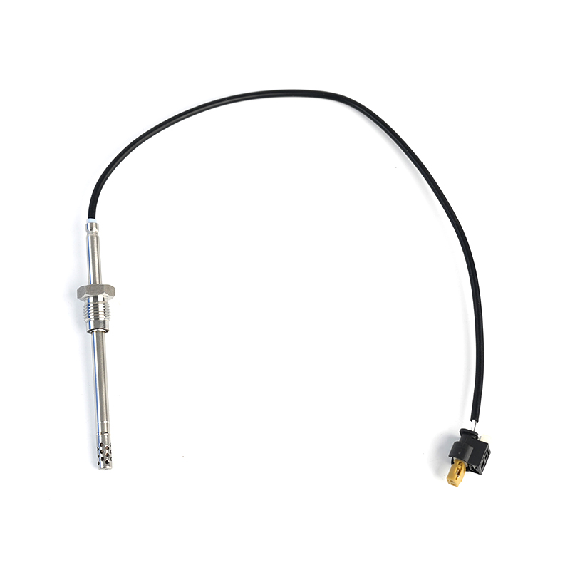
MERCEDES-BENZC-CLASS (W203) (2000/05 - 2007/08)MERCEDES-BENZC-CLASS Coupe (CL203) (2001/03 - 2011/06...
See Details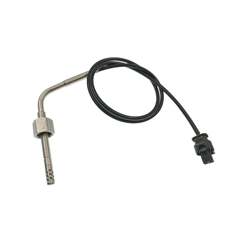
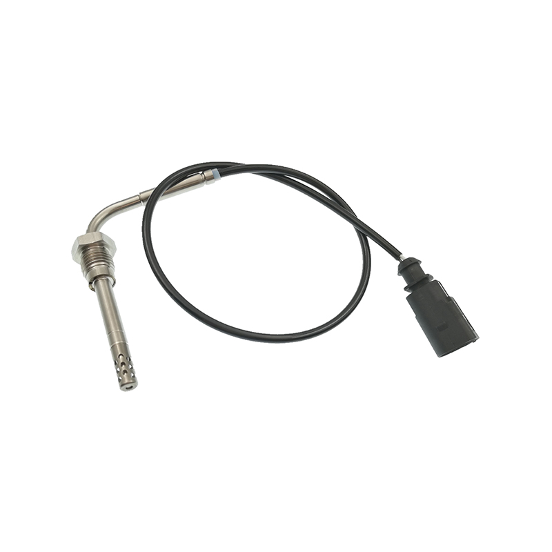
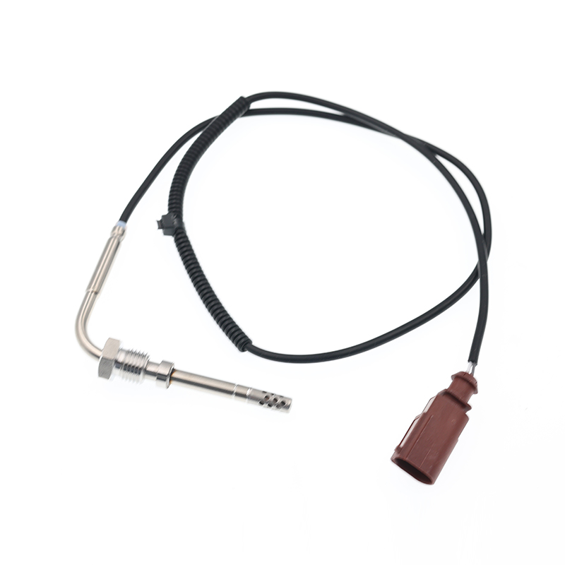
AUDIQ7 (4L) (2006/03 - 2015/08)VWTOUAREG (7LA, 7L6, 7L7) (2002/10 - 2010/05)
See Details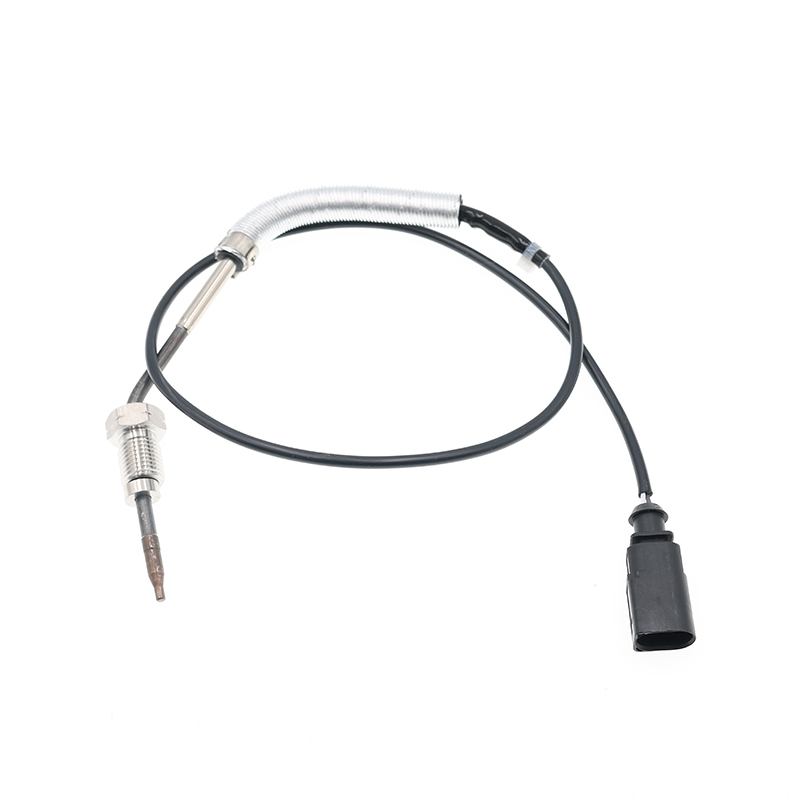
AUDIA3 (8P1) (2003/05 - 2012/08)AUDIA3 Sportback (8PA) (2004/09 - 2013/03)AUDIA4 (8EC, B7) (2004/11 ...
See Details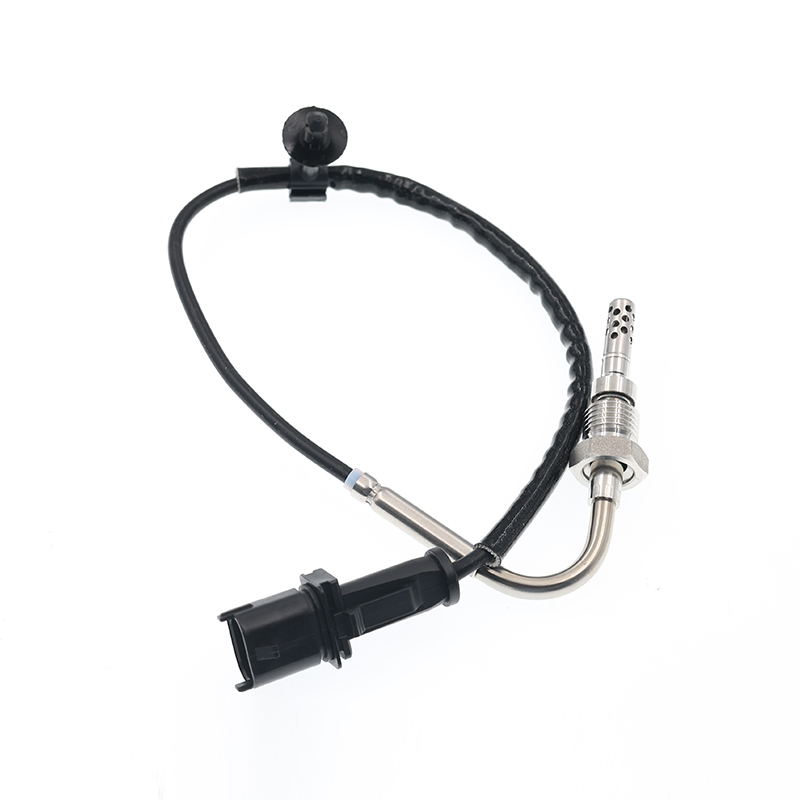
OPEL ASTRA J (2009/12 - /) OPEL ASTRA J Sports Tourer (2010/10 - /) OPEL ASTRA GTC J ...
See Details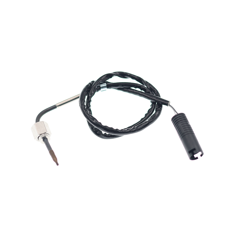
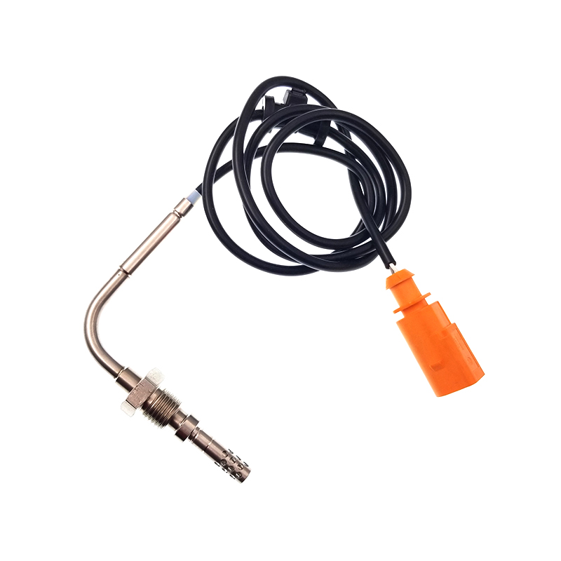
VWJETTA III (1K2) (2005/08 - 2010/10) VWGOLF VI (5K1) (2008/10 - 2013/11) VWGOLF VI Varia...
See Details
ADD: No.85 Jiuyuan Road, Economic Development Zone, Gaoyou city ,Yangzhou city ,225600 Jiangsu Province, China.
Copyright © Sook High Tech (Jiangsu) Co., Ltd. All Rights Reserved. OEM/ODM Automotive Sensor Manufacturers

