 English
 Español
 Français
 简体中文
简体中文ADD: No.85 Jiuyuan Road, Economic Development Zone, Gaoyou city ,Yangzhou city ,225600 Jiangsu Province, China.
MERCEDES-BENZC-CLASS (W203) (2000/05 - 2007/08)MERCEDES-BENZC-CLASS Coupe (CL203) (2001/03 - 2011/06...
See DetailsContent
A NOx sensor measures nitrogen oxide concentrations in exhaust gas and is critical for SCR (Selective Catalytic Reduction) systems to function correctly. When it fails, the engine management system triggers fault codes, and in many cases the vehicle enters limp mode or fails emissions testing. This guide covers everything from sensor types and operating principles to diagnostics, repair, and maintenance — with concrete data and real-world examples throughout.
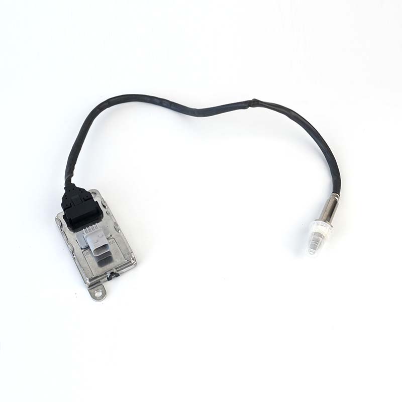
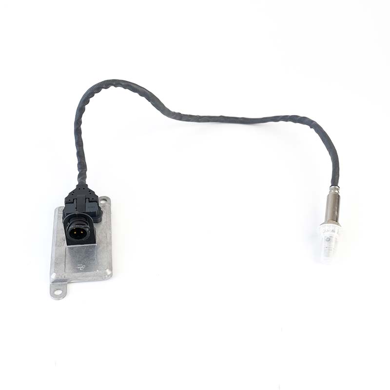
NOx sensors are not one-size-fits-all. The type installed depends on vehicle platform, exhaust aftertreatment architecture, and OEM specification. The three most common categories are:
| Type | Location | Primary Function | Typical Signal |
|---|---|---|---|
| Upstream | Before SCR catalyst | Engine-out NOx measurement | 0.1 – 4.9 V |
| Downstream | After SCR catalyst | Catalyst efficiency verification | 0.1 – 4.9 V |
| Combined NOx/O₂ | Before or after catalyst | Dual-parameter measurement | CAN bus digital |

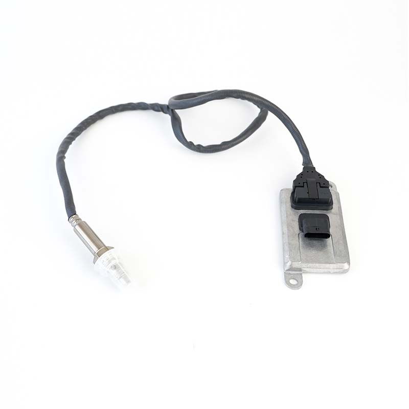
Most modern NOx sensors use a dual-cell electrochemical measurement principle based on zirconia (ZrO₂) solid electrolyte technology — the same material used in wideband lambda sensors, but with an additional pumping stage.
Exhaust gas enters a first diffusion chamber. An electrochemical pump cell removes excess oxygen by applying a precisely controlled current. This step is essential because residual O₂ would interfere with NOx measurement. The oxygen partial pressure in this chamber is regulated to approximately 10⁻⁷ bar.
The oxygen-depleted gas passes into a second chamber where a catalytically active electrode decomposes NO and NO₂ into nitrogen and oxygen ions. The resulting ion current is directly proportional to the NOx concentration. The ECU converts this current signal into a ppm value, typically ranging from 0 to 3,000 ppm for heavy-duty applications and 0 to 1,500 ppm for passenger vehicles.
Because the sensor output is a CAN bus digital signal in newer designs, signal integrity is higher and less susceptible to wiring resistance compared to older analog voltage-based systems.
The zirconia electrolyte only achieves adequate ionic conductivity at temperatures above 600 °C. To reach this operating temperature quickly and maintain it precisely, every NOx sensor incorporates a ceramic PTC (Positive Temperature Coefficient) heating element.
If the heater circuit fails, the ECU will log a heater performance fault (e.g., P0544 or manufacturer-specific DTC) and the SCR system cannot operate correctly until the sensor is replaced.
Correct installation is critical. A mishandled sensor can fail within hours. Follow this sequence:
On some platforms (notably DAF, Volvo, and Scania trucks), an ECU parameter reset or variant coding is required after sensor replacement. Skipping this step causes persistent fault codes even with a fully functional new sensor.
Start with a live data scan before replacing anything. Many NOx sensor faults are caused by wiring defects, contaminated AdBlue, or SCR catalyst failure — not the sensor itself.
| Fault Code | Description | Most Likely Cause |
|---|---|---|
| P229F | NOx sensor 1 circuit range/performance | Contaminated or aged sensor element |
| P2201 | NOx sensor circuit range/performance (bank 1) | Wiring short or open circuit |
| P2209 | NOx sensor heater circuit performance | Failed heater element or PWM driver fault |
| P204F | Reductant system performance | SCR catalyst failure, incorrect AdBlue |
The following is a representative example of a diagnostic session on a Euro 6 diesel passenger vehicle with a persistent P229F fault using VCDS (VAG-COM Diagnostic System):
This example illustrates why live data comparison and a resistance check together confirm the faulty component before purchase — avoiding unnecessary SCR catalyst replacement which can cost over €1,500.
NOx sensors are classified as a wear item with a typical service life of 160,000 – 200,000 km under normal operating conditions. Harsh duty cycles, EGR fouling, or oil ash contamination can reduce this significantly.
NOx sensors are not serviceable at element level. If the electrochemical cell or heater is faulty, the sensor assembly must be replaced. However, the following components can be repaired without sensor replacement:
Short distances are possible, but the vehicle will typically illuminate the MIL (Check Engine Light) and may enter a reduced power or limp mode after a defined number of drive cycles with the fault active. In jurisdictions with OBD-based emissions testing, a stored NOx fault will cause an immediate test failure.
NOx sensors cannot be field-calibrated. If live data shows a frozen reading, erratic signal, or a reading that deviates by more than 15% from expected values after a verified drive cycle, replacement is the correct action. Some ECUs perform an internal offset correction at startup, but this compensates only for minor drift.
Reputable Tier 1 aftermarket suppliers (Bosch, NGK/NTK, Delphi) produce sensors to OEM specification and are generally reliable. Low-cost unbranded sensors from unknown manufacturers frequently exhibit calibration offset errors of 10 – 30% from new, causing persistent fault codes or incorrect SCR dosing. Always verify part compatibility and source from established suppliers.
The most common reasons are: failure to clear adaptation data or perform variant coding after installation, a deteriorated SCR catalyst that the new sensor correctly identifies as underperforming, or an underlying EGR or fuel system fault generating abnormally high NOx that exceeds the sensor's expected range. Always perform a complete system diagnostic — not just a sensor swap — when a fault reappears on a new sensor.
OEM sensor prices range from €120 – €350 for passenger vehicles and up to €600 – €900 for heavy commercial vehicles. Labour typically adds 1 – 2 hours at workshop rates. Aftermarket alternatives from Tier 1 suppliers cost 30 – 50% less while maintaining equivalent performance.

MERCEDES-BENZC-CLASS (W203) (2000/05 - 2007/08)MERCEDES-BENZC-CLASS Coupe (CL203) (2001/03 - 2011/06...
See Details


AUDIQ7 (4L) (2006/03 - 2015/08)VWTOUAREG (7LA, 7L6, 7L7) (2002/10 - 2010/05)
See Details
AUDIA3 (8P1) (2003/05 - 2012/08)AUDIA3 Sportback (8PA) (2004/09 - 2013/03)AUDIA4 (8EC, B7) (2004/11 ...
See Details
OPEL ASTRA J (2009/12 - /) OPEL ASTRA J Sports Tourer (2010/10 - /) OPEL ASTRA GTC J ...
See Details

VWJETTA III (1K2) (2005/08 - 2010/10) VWGOLF VI (5K1) (2008/10 - 2013/11) VWGOLF VI Varia...
See DetailsADD: No.85 Jiuyuan Road, Economic Development Zone, Gaoyou city ,Yangzhou city ,225600 Jiangsu Province, China.
Copyright © Sook High Tech (Jiangsu) Co., Ltd. All Rights Reserved. OEM/ODM Automotive Sensor Manufacturers

