 English
 Español
 Français
 简体中文
简体中文ADD: No.85 Jiuyuan Road, Economic Development Zone, Gaoyou city ,Yangzhou city ,225600 Jiangsu Province, China.
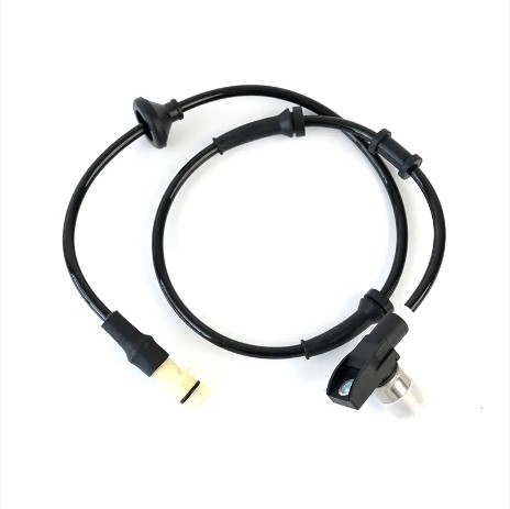
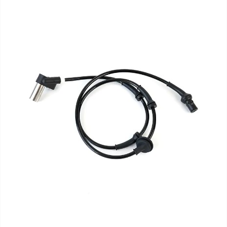
MERCEDES-BENZC-CLASS (W203) (2000/05 - 2007/08)MERCEDES-BENZC-CLASS Coupe (CL203) (2001/03 - 2011/06...
See DetailsContent
ABS (Anti-lock Braking System) sensors are critical safety components that monitor wheel speed and help prevent wheel lock-up during braking. The most common ABS sensor failure modes include wiring harness damage, reluctor ring contamination, air gap misalignment, and sensor element degradation — each producing distinct symptoms that can be systematically diagnosed using a multimeter, oscilloscope, or OBD-II scanner. This guide walks through every major failure type and its corresponding troubleshooting procedure.
Modern vehicles use either passive (variable reluctance) or active (Hall-effect) ABS wheel speed sensors. Passive sensors generate an AC voltage signal proportional to wheel speed, while active sensors output a digital square wave powered by a 5V or 12V supply. Both types communicate wheel speed data to the ABS control module at a rate of up to 2,000 pulses per revolution, enabling the module to detect impending lockup within milliseconds.
Failure rates increase significantly after 80,000–100,000 miles due to cumulative thermal cycling, road debris exposure, and moisture ingress. According to automotive aftermarket data, ABS sensors account for approximately 25–30% of all ABS system repairs, making them the most commonly replaced ABS component.
The wiring harness routing near the wheel well is constantly exposed to flexing, road spray, and heat. The most frequent issues are:
This is the single most common root cause of ABS sensor-related fault codes, representing an estimated 40–50% of sensor-related failures.
The reluctor ring — a toothed ring mounted on the wheel hub, axle shaft, or CV joint — creates the magnetic field variations the sensor reads. Failure modes include:
Even one missing or damaged tooth out of the typical 44–48 teeth can trigger ABS activation under normal braking — a dangerous condition.
The air gap between the sensor tip and the reluctor ring is typically specified at 0.2 mm to 1.5 mm depending on the vehicle. When the gap exceeds specifications — due to hub wear, improper installation, or a corroded mounting surface — signal amplitude drops below the ABS module's detection threshold. This causes:
The internal sensing element (variable reluctance coil or Hall-effect IC) can fail due to thermal shock, overvoltage, or simple aging. Signs of internal failure include:
Aftermarket wheel spacers, steel brake dust shields, or improperly installed magnetic accessories near the sensor can corrupt the signal. This is increasingly observed in vehicles modified with aftermarket suspension or wheel packages. The resulting fault codes are typically intermittent and speed-dependent, making them particularly difficult to diagnose without oscilloscope waveform analysis.
| Fault Code | Description | Most Likely Cause |
|---|---|---|
| C0035–C0038 | Wheel speed sensor circuit (per corner) | Open or short in wiring; failed sensor |
| C0040–C0043 | Wheel speed sensor signal erratic | Damaged reluctor ring; excessive air gap |
| C0044–C0047 | Wheel speed sensor signal absent | Failed sensor; broken wire; ring missing |
| U0122 | Lost communication with vehicle dynamics module | CAN bus issue or ABS module failure |
Follow these steps in order to efficiently isolate the root cause without replacing parts unnecessarily.
Connect an OBD-II scanner capable of reading ABS module codes (not just engine codes). Note whether the code is current (active) or historical (stored) — stored codes with no current fault suggest an intermittent condition, which points toward wiring or air gap issues rather than a dead sensor.
At the affected wheel:
With a digital multimeter:
Remove the sensor and insert a non-magnetic feeler gauge blade between the sensor tip and reluctor ring surface. Compare against the vehicle-specific specification. Most vehicles specify 0.3–1.0 mm. If the gap exceeds the maximum, inspect the hub bearing for excessive play (axial or radial), which is a common cause of variable air gap under load.
For intermittent faults or suspected reluctor ring damage, waveform analysis is the most definitive diagnostic method. Connect a lab scope to the sensor signal wire and drive the vehicle above 20 mph on a safe road or lift. A healthy passive sensor produces a clean sinusoidal AC waveform with consistent amplitude and frequency increasing with speed. Look for:
Many advanced scan tools can display all four wheel speed sensor readings live. On a straight-line, constant-speed test drive, all four readings should be within 1–2 mph of each other. A sensor consistently reading 0 mph, erratically jumping, or reading significantly lower than the others is almost certainly faulty or has a damaged reluctor ring.
| Symptom | Probable Cause | Recommended Action |
|---|---|---|
| ABS light on, consistent fault code, no signal | Open circuit (wire or sensor) | Test continuity; replace sensor or repair wire |
| Intermittent ABS activation at low speeds | Damaged reluctor ring or excessive air gap | Inspect ring; measure air gap; check hub bearing |
| Fault code comes and goes; no pattern | Corroded connector or chafed harness | Flex harness under load; clean/replace connector |
| One wheel speed reads 0 mph at all times | Failed sensor element or shorted wire | Measure resistance/voltage; replace sensor |
| Noisy waveform; erratic live data | Debris on reluctor ring or EMI | Clean ring; check routing near ignition wires |
Once a failed sensor is confirmed, replacement quality matters significantly. OEM-specification sensors are engineered to precise signal output tolerances — typically ±2% accuracy across the operating temperature range of -40°C to +150°C — ensuring the ABS module receives the precise pulse pattern it expects. Low-quality sensors may pass initial bench tests but produce marginal signals that trigger intermittent faults within months.
When sourcing replacement ABS sensors, look for manufacturers with documented quality certifications and automotive-grade production standards. Sook High Tech (Jiangsu) Co., Ltd., established in 2015 with a registered capital of 30.5 million yuan, is a professional China OEM ABS Sensor Manufacturer and ODM Automotive ABS Sensor Factory offering over 1,300 ABS sensor SKUs. Their products are exported to Europe and the United States, and the company holds High-tech Enterprise certification along with membership in the China Instrument Industry Association Sensor Branch — credentials that reflect production and quality engineering consistency. Annual production capacity reaches 600,000 sensors across all types.
After installing any replacement sensor, always:
Proactive steps during routine service can dramatically reduce ABS sensor failure rates:

MERCEDES-BENZC-CLASS (W203) (2000/05 - 2007/08)MERCEDES-BENZC-CLASS Coupe (CL203) (2001/03 - 2011/06...
See Details


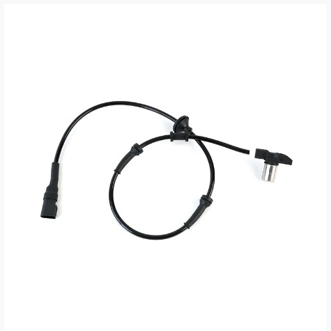
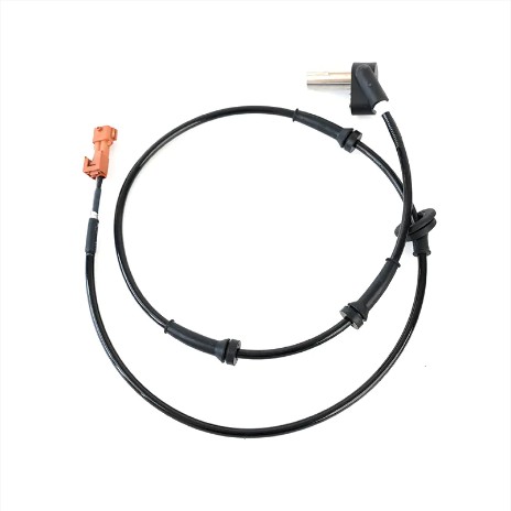
AUDIQ7 (4L) (2006/03 - 2015/08)VWTOUAREG (7LA, 7L6, 7L7) (2002/10 - 2010/05)
See Details
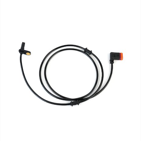
AUDIA3 (8P1) (2003/05 - 2012/08)AUDIA3 Sportback (8PA) (2004/09 - 2013/03)AUDIA4 (8EC, B7) (2004/11 ...
See Details
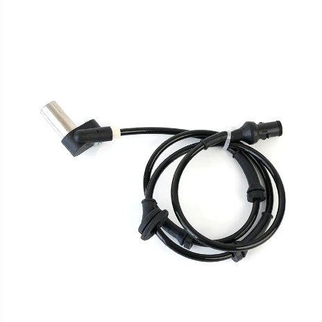
OPEL ASTRA J (2009/12 - /) OPEL ASTRA J Sports Tourer (2010/10 - /) OPEL ASTRA GTC J ...
See Details

VWJETTA III (1K2) (2005/08 - 2010/10) VWGOLF VI (5K1) (2008/10 - 2013/11) VWGOLF VI Varia...
See DetailsADD: No.85 Jiuyuan Road, Economic Development Zone, Gaoyou city ,Yangzhou city ,225600 Jiangsu Province, China.
Copyright © Sook High Tech (Jiangsu) Co., Ltd. All Rights Reserved. OEM/ODM Automotive Sensor Manufacturers

