
 English
 Español
 Français

 简体中文
ADD: No.85 Jiuyuan Road, Economic Development Zone, Gaoyou city ,Yangzhou city ,225600 Jiangsu Province, China.
MERCEDES-BENZC-CLASS (W203) (2000/05 - 2007/08)MERCEDES-BENZC-CLASS Coupe (CL203) (2001/03 - 2011/06...
See DetailsContent
Start with the loop, not the gains. A PID controller only trims what the sensor, the actuator and the process already allow, so the useful question is not "what are the best numbers" but "what is my loop actually measuring, and how fast can it move?" Warm a 2 kW heater block with a probe that lags 30 seconds behind the block and no combination of P, I and D will deliver a clean step to 200 °C.
The working order is remarkably stable across temperature, pressure, flow and motion loops: characterise the process in manual, raise proportional action until the response is quick but not hunting, add integral action to remove the offset that proportional control leaves behind, then add derivative action only if overshoot still costs you money. Every step ends with a measurement, not an opinion.
What follows is the sequence we recommend for real equipment, including the parts most guides skip: sampling time, output limits, sensor lag, and what to do when a loop behaves well at one setpoint and badly at another.
Gains applied to a badly configured loop produce confusing results, and the confusion usually gets blamed on the controller. Five settings deserve a check first:
Write the settings down before you change anything. A baseline of setpoint, ambient condition, output percentage and settling time turns tuning from trial and error into a comparison, and the second loop you commission will take half the time.
Each term reacts to a different version of the same error signal — the gap between setpoint and measurement — and each one has a characteristic failure mode when pushed too far.
| Term | Reacts to | Raise it when | Too much causes |
|---|---|---|---|
| Proportional (P) | Present error | Approach is sluggish and offset is acceptable | Continuous oscillation, actuator wear |
| Integral (I) | Error accumulated over time | Steady-state offset never disappears | Slow hunting, windup after saturation |
| Derivative (D) | Rate of change of error | Overshoot on a step still costs quality | Amplified sensor noise, jittery output |
Proportional action answers the error now, integral answers the error so far, derivative answers how fast it is changing.
A loop cannot correct faster than it can measure — a probe that needs 20 seconds to reach 63% of a step caps the achievable settling time, whatever the gains say.
Three properties of the feedback signal decide how much tuning room you have: response time, noise and drift. Response time comes mostly from mechanical design — sheath diameter, wall thickness, tip construction and how deep the probe sits in the medium. A 3 mm sheathed thermocouple reacts far faster than a 6 mm probe in the same pipe, and an exposed junction faster still, at the cost of protection.
Noise shows up in the derivative term first. Screen and twist signal leads, ground at one end only, and use mineral-insulated cable with a grounded sheath where temperature or electromagnetic interference is high. If the loop chatters with D at zero, the problem is wiring or sampling, not tuning.
Drift and accuracy decide whether the setpoint can be held at all. Thermistor elements give strong sensitivity over a narrow band, thermocouples cover wide ranges with fast response, and RTDs trade speed for stability. Match the element to the band you actually run in, and check that the sheath material survives the atmosphere.
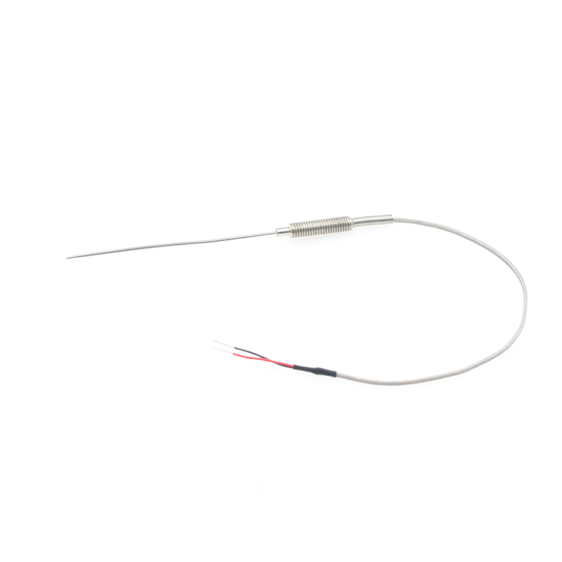 Thermocouple Temperature Sensor Variants for Industrial UseBrowse K, N, E, J, T and other thermocouples covering -200°C to 1800°C, with selectable probes, sheaths and connection styles.View Product →
 RTD and Thermistor Temperature Sensors for Industrial UseCompare PT100, PT1000, Cu50 and Cu100 options with accuracy grades A–C and response times from 1 to 30 seconds for industrial temperature sensing.View Product →
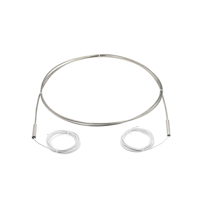 230V 1500W Armored Heater for Industrial FieldsReview a 230V 1500W armored heater with listed insulation and high-voltage test results, quote and contact options for industrial-field use.View Product →
Where a loop is limited by the sensing element rather than the controller, it is worth matching probe geometry and heater design to the process instead of compensating with gain. Range, sheath and response requirements can be reviewed through direct contact with the engineering team.
Most struggling loops fall into a small number of patterns. Find the symptom, apply the fix, then repeat the step test rather than re-tuning blindly.
| Symptom | Fix |
|---|---|
| Output pins at 100% for minutes, then overshoots badly | Add anti-windup: clamp or freeze the integral while the output is at its limit |
| Calm at low setpoint, hunting at high setpoint | Tune at the point of highest process gain, or schedule gains per range |
| Actuator chatters as soon as derivative is added | Reduce D, add a measurement filter, and check shielding and grounding |
| Offset never disappears no matter how P is set | Integral may be disabled, or an output limit sits below what the load needs |
| Two controllers fight over one heater | Use split-range or cascade so only one loop owns the actuator at a time |
If a loop still misbehaves after these checks, escalate with data rather than opinion — a trend of setpoint, measurement and output percentage over one full cycle usually identifies the cause in minutes. The technical support page is a sensible starting point for sensor-side questions.
Tuning is a measurement exercise with a control algorithm attached. Every gain you change should be a hypothesis about how the process responds, and every hypothesis needs a step test to confirm it. Loops that are documented, validated at their operating extremes and matched to a sensing element with the right response time keep working long after the fashionable numbers have been forgotten.
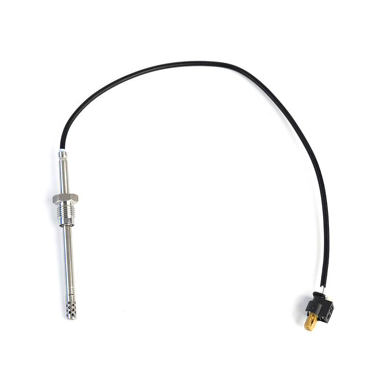
MERCEDES-BENZC-CLASS (W203) (2000/05 - 2007/08)MERCEDES-BENZC-CLASS Coupe (CL203) (2001/03 - 2011/06...
See Details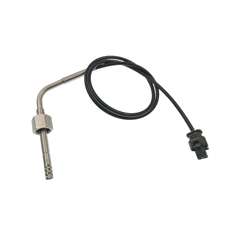
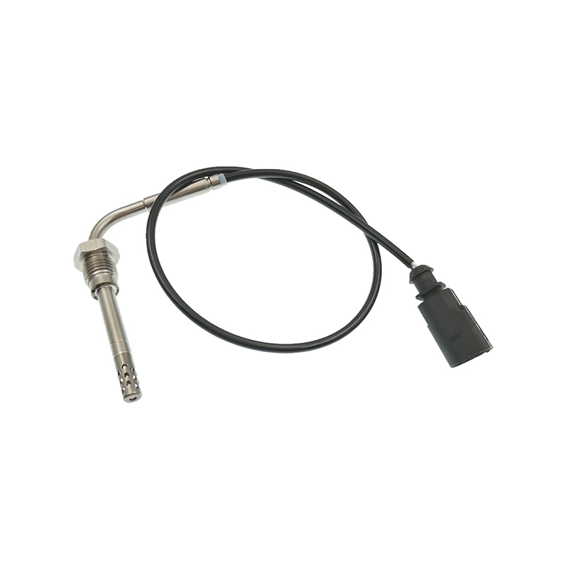
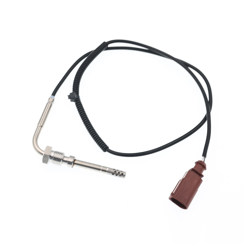
AUDIQ7 (4L) (2006/03 - 2015/08)VWTOUAREG (7LA, 7L6, 7L7) (2002/10 - 2010/05)
See Details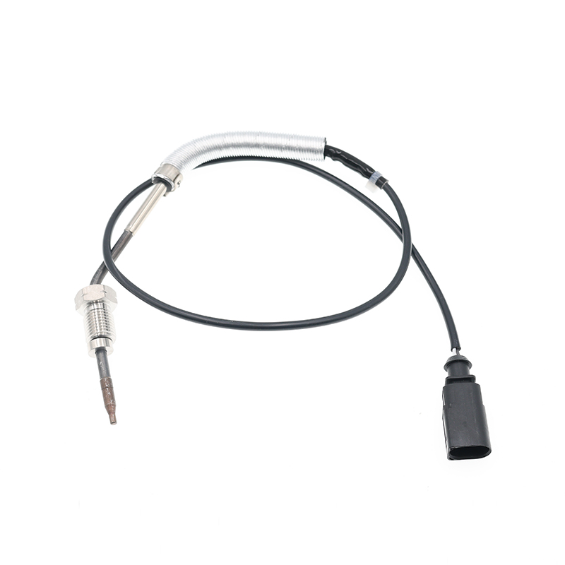
AUDIA3 (8P1) (2003/05 - 2012/08)AUDIA3 Sportback (8PA) (2004/09 - 2013/03)AUDIA4 (8EC, B7) (2004/11 ...
See Details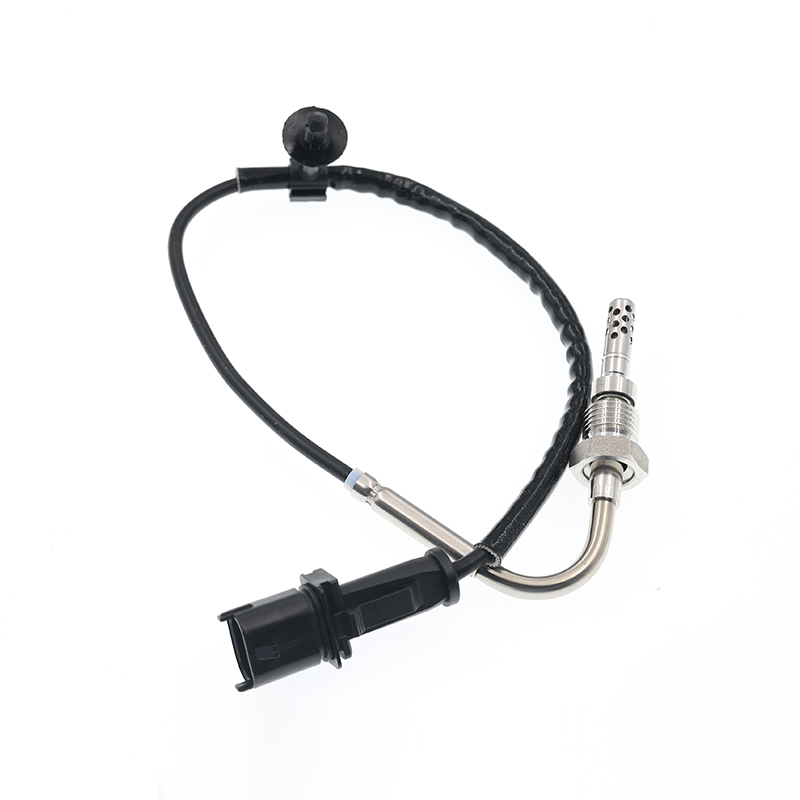
OPEL ASTRA J (2009/12 - /) OPEL ASTRA J Sports Tourer (2010/10 - /) OPEL ASTRA GTC J ...
See Details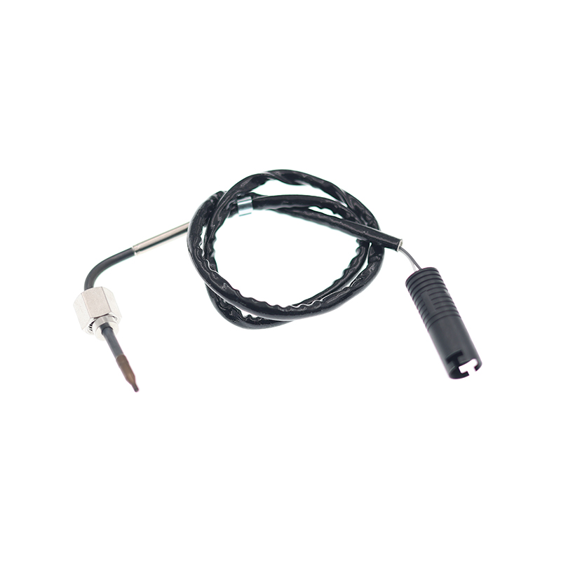
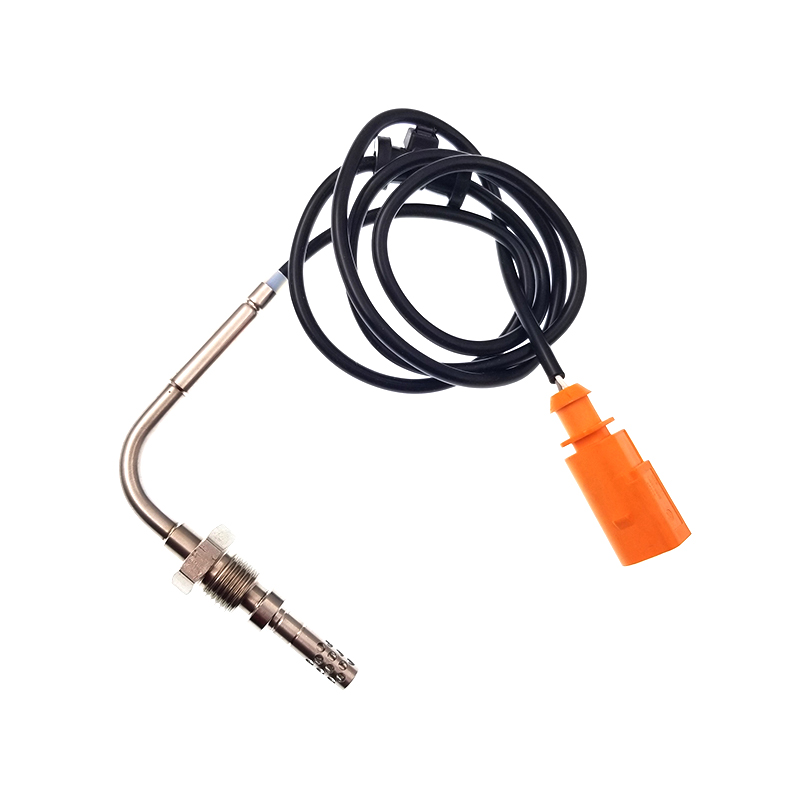
VWJETTA III (1K2) (2005/08 - 2010/10) VWGOLF VI (5K1) (2008/10 - 2013/11) VWGOLF VI Varia...
See Details
ADD: No.85 Jiuyuan Road, Economic Development Zone, Gaoyou city ,Yangzhou city ,225600 Jiangsu Province, China.
Copyright © Sook High Tech (Jiangsu) Co., Ltd. All Rights Reserved. OEM/ODM Automotive Sensor Manufacturers

