
 English
 Español
 Français

 简体中文
ADD: No.85 Jiuyuan Road, Economic Development Zone, Gaoyou city ,Yangzhou city ,225600 Jiangsu Province, China.
MERCEDES-BENZC-CLASS (W203) (2000/05 - 2007/08)MERCEDES-BENZC-CLASS Coupe (CL203) (2001/03 - 2011/06...
See DetailsContent
A 15 kW pump motor can sound normal while a failing outer-race bearing is already generating energy at several kilohertz—well above the 25 Hz shaft rotation you hear.
For motor vibration monitoring, the sensor is not a generic accessory. Select for frequency range, mounting quality, environment and signal interface first; then confirm sensitivity and certification. A 100 mV/g IEPE accelerometer is a common starting point for general machine monitoring, but it is a poor choice if the cable run is long, the surface is hot, or the fault you care about sits below 10 Hz. Conversely, a low-cost MEMS sensor can be perfectly adequate for trend monitoring on a fan motor when its bandwidth and noise floor are checked against the fault frequencies.
The practical consequence is simple: the same motor may need an accelerometer on the drive-end bearing, a proximity probe for shaft-relative motion, or a velocity sensor for low-speed imbalance—or a combination. Decide what you need to detect before comparing datasheets.
Motor vibration work usually falls into one of four sensor families. The table is a screening tool, not a substitute for a frequency-domain check against actual shaft speed, bearing geometry and expected fault bands.
| Route | Typical bandwidth | Best for | Mounting note | Main limitation |
|---|---|---|---|---|
| IEPE piezoelectric accelerometer | Often 0.5 Hz to 10 kHz and beyond | Bearing and gear faults, general condition monitoring | Stud or adhesive pad preferred; magnetic bases can reduce high-frequency response | Needs IEPE supply and careful cable and connector protection |
| MEMS accelerometer | Often DC to 1 kHz, with some models reaching a few kHz | Cost-sensitive trend monitoring, low-frequency imbalance | PCB or bracket mounting; protect from oil and coolant | Lower high-frequency resolution and different noise behaviour |
| Eddy current proximity probe | Shaft displacement over a wide dynamic range | Sleeve-bearing shaft motion, orbit and runout checks | Rigid bracket, correct target material and calibrated gap | Measures shaft motion, not casing high-frequency vibration |
| Velocity coil sensor | Typically 10 Hz to 1 kHz | Low-speed machines and overall casing vibration | Check orientation; use a rigid mounting surface | Limited high-frequency coverage and larger physical size |
Bandwidth figures are typical starting points; always confirm the actual response curve and environmental limits for the selected model.
Rolling-bearing defect energy commonly appears in the 1–10 kHz range and above. If the sensor, mounting and cable path cannot preserve that band, a higher nominal sensitivity will not recover the missing information.
A magnetic base is convenient for a quick survey, but it can act as a mechanical low-pass filter. On a critical motor, compare a stud-mounted reading with a magnetic-base reading before trusting the latter for high-frequency diagnosis. Surface flatness, torque and couplant also matter: a painted or curved surface may reduce repeatability even when the sensor itself is accurate.
Use a clean, flat, bare-metal spot and tighten the sensor or stud to the manufacturer’s torque. Route cable with strain relief, keep signal cable away from drive output cables where practical, and check for ground loops when readings contain unexpected mains-frequency noise.
| Common issue | Practical correction |
|---|---|
| Choosing by price before defining the fault frequency | Write down the target bands and require a response curve and noise specification |
| Using a magnetic base on every measurement | Reserve it for screening; use stud or adhesive mounting for trending and diagnosis |
| Comparing readings taken at different load or temperature | Record operating state and compare only like-for-like conditions |
| Ignoring cable and connector condition | Inspect shielding, strain relief and moisture ingress during every route check |
Most bad vibration data is traceable to a changed measurement chain, not to a sudden motor fault.
For projects that need custom interfaces or stable OE-compatible supply, reviewing a manufacturer’s sensor development and production background and asking technical support for the interface drawing, test report and sample evaluation plan is more useful than comparing only a headline price.
Lock out and tag out the drive before installing or adjusting a sensor on a motor that can start automatically. A vibration reading is never worth reaching into a guarded area while the machine is running.
In hazardous areas, confirm the sensor, cable and barrier certification before installation. Keep cable routes away from hot surfaces and moving parts, and use a drip loop where condensation or washdown water is possible.
A good motor vibration sensor installation is repeatable, documented and matched to the fault it is meant to reveal. The sensor is mounted firmly, the cable is protected, the operating state is recorded, and the alarm threshold has an engineering reason behind it. When those basics are right, a modest sensor can outperform an expensive one installed with poor coupling and unclear measurement goals.
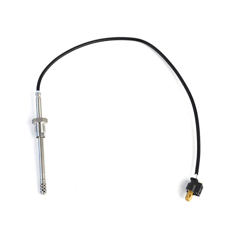
MERCEDES-BENZC-CLASS (W203) (2000/05 - 2007/08)MERCEDES-BENZC-CLASS Coupe (CL203) (2001/03 - 2011/06...
See Details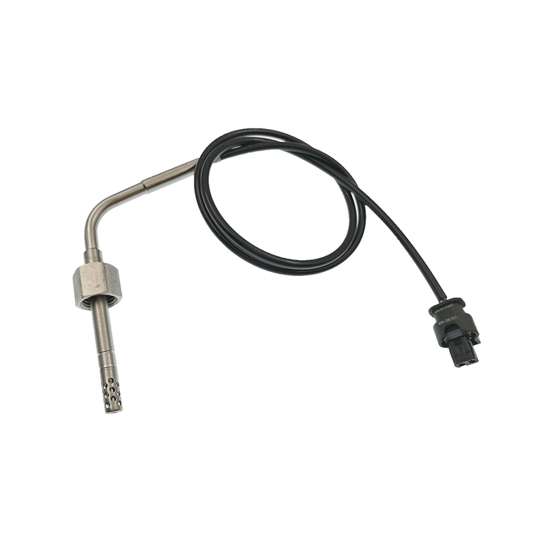
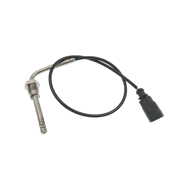
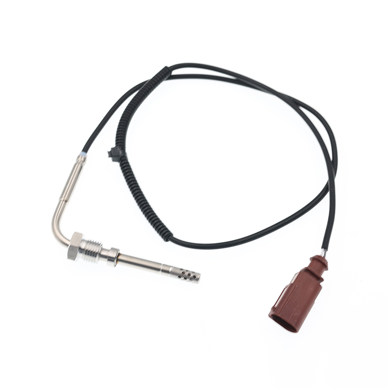
AUDIQ7 (4L) (2006/03 - 2015/08)VWTOUAREG (7LA, 7L6, 7L7) (2002/10 - 2010/05)
See Details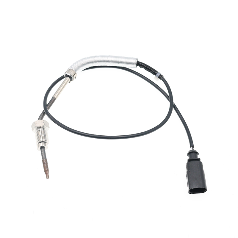
AUDIA3 (8P1) (2003/05 - 2012/08)AUDIA3 Sportback (8PA) (2004/09 - 2013/03)AUDIA4 (8EC, B7) (2004/11 ...
See Details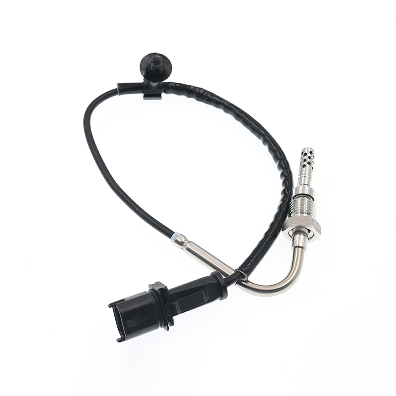
OPEL ASTRA J (2009/12 - /) OPEL ASTRA J Sports Tourer (2010/10 - /) OPEL ASTRA GTC J ...
See Details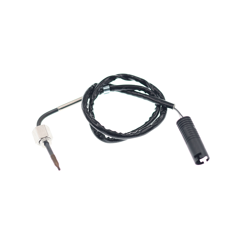
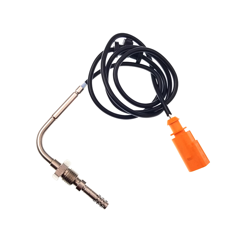
VWJETTA III (1K2) (2005/08 - 2010/10) VWGOLF VI (5K1) (2008/10 - 2013/11) VWGOLF VI Varia...
See Details
ADD: No.85 Jiuyuan Road, Economic Development Zone, Gaoyou city ,Yangzhou city ,225600 Jiangsu Province, China.
Copyright © Sook High Tech (Jiangsu) Co., Ltd. All Rights Reserved. OEM/ODM Automotive Sensor Manufacturers

