
 English
 Español
 Français
 简体中文
简体中文ADD: No.85 Jiuyuan Road, Economic Development Zone, Gaoyou city ,Yangzhou city ,225600 Jiangsu Province, China.
MERCEDES-BENZC-CLASS (W203) (2000/05 - 2007/08)MERCEDES-BENZC-CLASS Coupe (CL203) (2001/03 - 2011/06...
See DetailsContent
Electromagnetic interference usually shows up in the field as a symptom, not as a fault code: an exhaust gas temperature reading that drifts 30 °C when a cooling fan starts, an ABS lamp that lights up above 60 km/h, or a thermocouple channel that jumps every time a variable-frequency drive ramps up. In most of those cases the sensor is not the problem. The cable, the shield termination and the grounding scheme are.
If there is budget for only one change this quarter, make it a properly terminated shield on every low-level signal line. That single measure removes the majority of noise complaints, costs far less than a sensor upgrade programme, and does not require any change to the measurement electronics. Everything below is ordered from the cheapest and most effective method to the more specialised ones.
A type K thermocouple produces roughly 41 µV per °C at room temperature. An NTC exhaust gas temperature sensor may change only a few hundred millivolts across its whole working range. Against those numbers, a PWM motor cable running 100 mm away can inject several volts of common-mode noise, which is a thousand times larger than the signal being measured. No accuracy specification on a datasheet survives that environment on its own.
Three properties decide whether a harness behaves or not. The shield must enclose the conductors with no break from the sensor connector to the controller. The pair carrying the signal must be twisted so magnetic pickup cancels inside each loop. The shield must be bonded to the chassis with a low-impedance connection. A drain wire terminated through a 100 mm pigtail behaves like a small antenna and can leave a system noisier than an unshielded cable, so keep that pigtail under 25 mm and clamp the shield to the enclosure with a 360° gland or clamp.
Ground the shield at the controller end for slow signals below about 1 MHz, and ground it at both ends when the noise source is a PWM drive, an ignition system or a radio transmitter. If bonding both ends creates a ground loop current above a few amps, keep the far end grounded through a 10–100 nF capacitor rated for the working voltage, or break the loop with an isolated amplifier. The point is to give interference current a defined, short return path instead of letting it share the signal conductors.
The table below compares the methods that solve the majority of sensor and heater interference problems in vehicles and process plants. The right choice depends less on the sensor type than on the frequency of the noise and the temperature at the cable.
| Method | What It Suppresses | Best Fit | Watch Out For |
|---|---|---|---|
| Braid or foil shield with 360° termination | Electric field and RF pickup | EGT, NOx and ammonia sensor leads | Long pigtails turn the drain into an antenna |
| Shielded twisted pair | Magnetic and capacitive coupling | Millivolt thermocouple and bridge signals | Twist pitch above 50 mm loses most of the benefit |
| Single-point ground with isolated amplifier | Ground loops and common-mode voltage | Long runs between cabinets or buildings | Requires an isolated supply and careful layout |
| Mineral-insulated triaxial cable | Heat exposure plus RF and mechanical stress | Furnaces, nuclear and aerospace platforms | Higher cost and a wider minimum bend radius |
Method selection guide for low-level sensor signals exposed to drive, ignition or furnace interference.
Two cables with the same temperature rating and the same outer diameter can differ by a factor of fifty in noise performance. The figures below are the ones worth writing into a purchase specification, because they describe behaviour under interference rather than behaviour in a catalogue.
Shield coverage above 85 percent and transfer impedance below 10 mΩ/m at 1 MHz decide whether a low-level signal survives a drive cabinet next door, not the cable's temperature rating.
Transfer impedance describes how much of the current flowing on the shield couples into the inner conductor. A foil shield offers 100 percent coverage but little current capacity and cracks with repeated flexing; a braid is mechanically robust but typically covers 85 to 95 percent. Common-mode rejection ratio above 80 dB at 50 or 60 Hz is a reasonable minimum for a differential input, and a twist pitch of 50 mm or less is enough to cancel most magnetic pickup at power frequencies. Where a shield carries 10 A of ground-loop current at 50 Hz, expect tens of millivolts of induced noise on an unpaired return conductor.
Most interference problems found during commissioning trace back to the same handful of installation shortcuts. The table pairs each symptom with the correction that resolves it without replacing hardware.
| Problem | Correct Fix |
|---|---|
| Shield grounded at one end only on a drive-controlled machine | Bond both ends with 360° terminations, or add a 10–100 nF shield capacitor at the sensor end |
| Drain wire left long inside a junction box | Bond the shield to the enclosure within 25 mm of the connector entry |
| Signal and motor cables pulled through the same conduit | Separate them by at least 300 mm and cross only at 90° |
| Plain copper wire used to extend a thermocouple | Use shielded twisted extension wire with the matching alloy |
| Sensor housing isolated on a plastic standoff with no reference | Provide a defined reference and bond the sheath where the manufacturer permits |
Symptom-to-correction reference for commissioning and retrofit work on sensor harnesses.
Foil-and-drain construction has a practical ceiling. Above roughly 200 °C the jacket degrades, the foil cracks, and the shield stops being a shield. In exhaust gas temperature measurement, furnace control and nuclear signal paths, the shielding has to be part of the mechanical structure rather than something wrapped around it. A continuous metallic sheath with mineral insulation keeps the conductive barrier intact while surviving the same temperature and vibration that would destroy a polymer jacket.
That engineering approach is what SOOK High Tech builds at its own plants, with products such as a and a . Where the interference comes from a heater rather than a signal line, a limits radiated noise while still delivering the required watt density. Readers who want to see how these assemblies are produced can review the company background and the factory equipment pages, since sheath integrity and weld quality decide the final transfer impedance more than the datasheet does.
The practical conclusion is straightforward. Choose the shield topology that matches the noise frequency, terminate it with a low-impedance bond at the points written on the drawing, and select cable construction that keeps that barrier intact for the life of the equipment. Interference then behaves as a manageable design variable instead of an intermittent fault that nobody can reproduce.
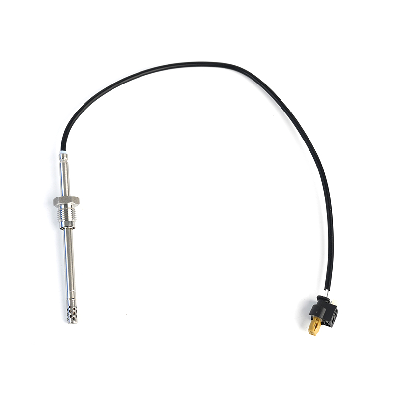
MERCEDES-BENZC-CLASS (W203) (2000/05 - 2007/08)MERCEDES-BENZC-CLASS Coupe (CL203) (2001/03 - 2011/06...
See Details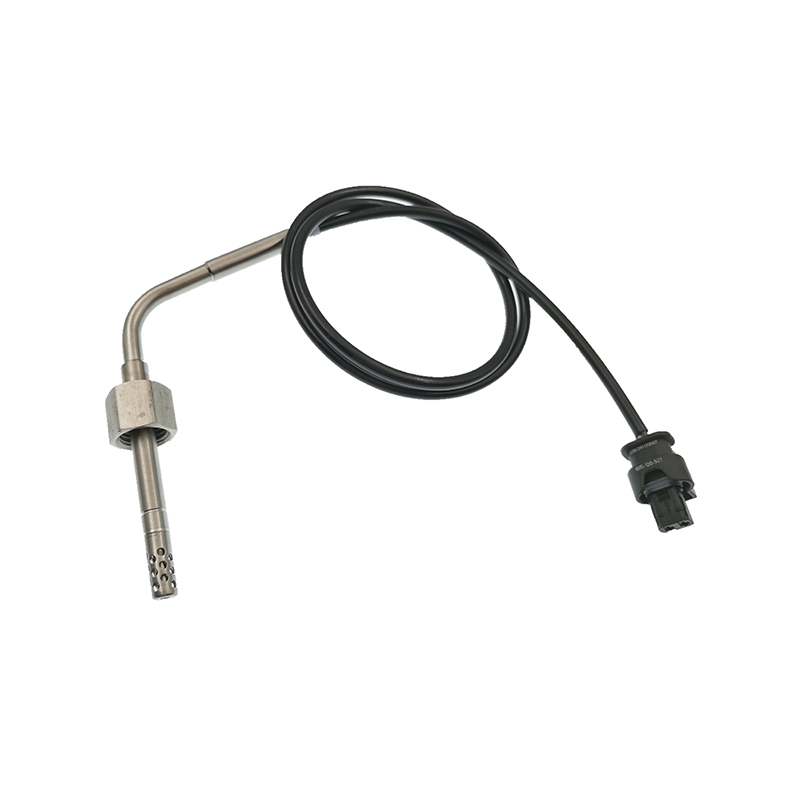
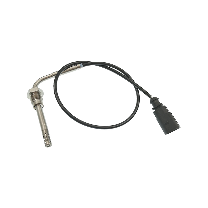
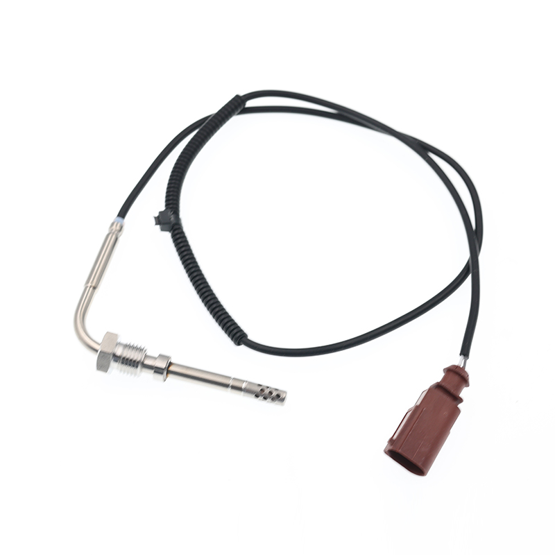
AUDIQ7 (4L) (2006/03 - 2015/08)VWTOUAREG (7LA, 7L6, 7L7) (2002/10 - 2010/05)
See Details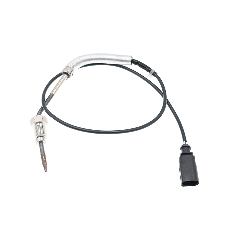
AUDIA3 (8P1) (2003/05 - 2012/08)AUDIA3 Sportback (8PA) (2004/09 - 2013/03)AUDIA4 (8EC, B7) (2004/11 ...
See Details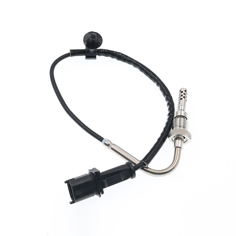
OPEL ASTRA J (2009/12 - /) OPEL ASTRA J Sports Tourer (2010/10 - /) OPEL ASTRA GTC J ...
See Details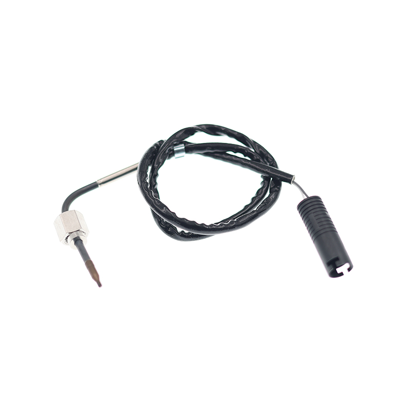
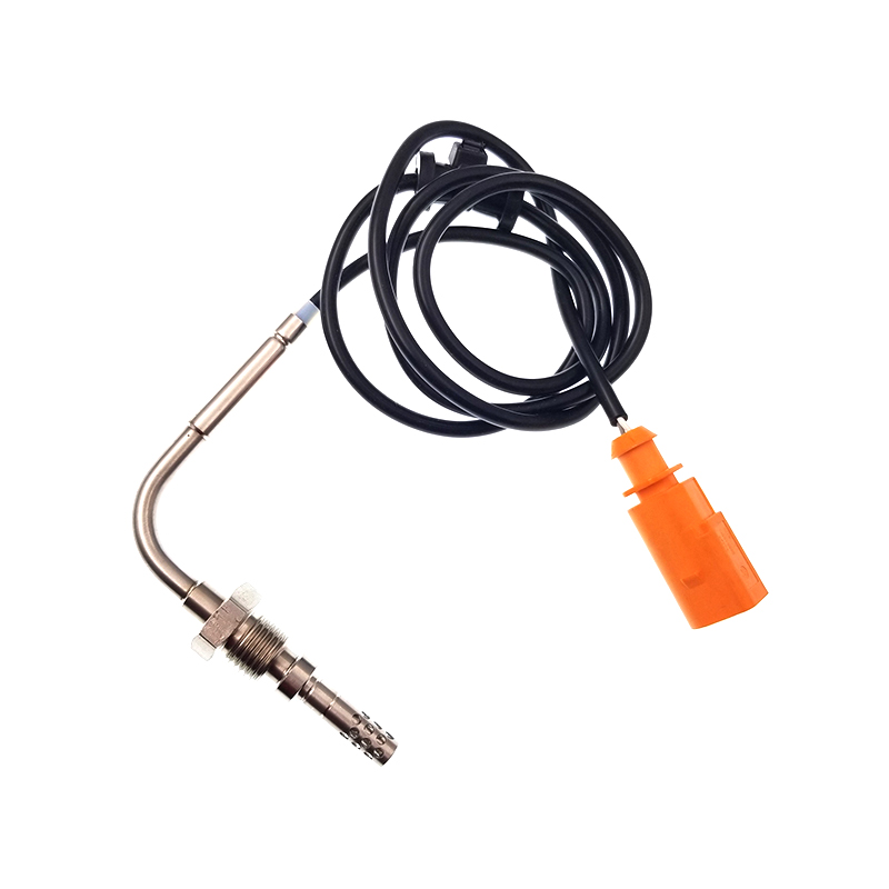
VWJETTA III (1K2) (2005/08 - 2010/10) VWGOLF VI (5K1) (2008/10 - 2013/11) VWGOLF VI Varia...
See Details
ADD: No.85 Jiuyuan Road, Economic Development Zone, Gaoyou city ,Yangzhou city ,225600 Jiangsu Province, China.
Copyright © Sook High Tech (Jiangsu) Co., Ltd. All Rights Reserved. OEM/ODM Automotive Sensor Manufacturers

