
 English
 Español
 Français
 简体中文
简体中文ADD: No.85 Jiuyuan Road, Economic Development Zone, Gaoyou city ,Yangzhou city ,225600 Jiangsu Province, China.
MERCEDES-BENZC-CLASS (W203) (2000/05 - 2007/08)MERCEDES-BENZC-CLASS Coupe (CL203) (2001/03 - 2011/06...
See DetailsContent
A resistance sensor, more precisely called a thermal resistance temperature sensor, measures temperature by tracking how the electrical resistance of a conductor or semiconductor changes as temperature changes. These sensors fall into two broad categories: metal thermal resistors, commonly known as RTDs, and semiconductor thermistors. Together they cover a working range of roughly -200°C to 850°C, making them one of the most widely used temperature measurement technologies in industrial and automotive systems.
The core principle is simple: as temperature rises, a metal RTD's resistance increases in a predictable, near-linear way, while a semiconductor thermistor's resistance typically drops sharply. Measuring that resistance change and converting it through a known formula gives an accurate temperature reading without needing a direct thermal contact reaction, which is what makes resistance sensors durable and repeatable over long service periods.
Unlike thermocouples, which generate a small voltage signal from the junction of two dissimilar metals, resistance sensors rely purely on a passive resistive element. This means they require an external excitation current to produce a measurable signal, but in return they typically deliver better long-term stability and repeatability, since there is no junction degradation to worry about over time.
Temperature is one of the most frequently monitored variables in industrial processes, and inaccurate readings can lead to product defects, safety incidents, or unplanned downtime. Resistance sensors are chosen specifically because their output follows a well-documented, standardized curve, which allows different instruments and control systems to interpret the same resistance value consistently across a plant or a supply chain.
This standardization is especially important in regulated sectors such as chemical processing, oil and gas, and automotive emissions control, where a drift of even a few tenths of a degree in a temperature reading can trigger incorrect process adjustments or false alarms. Because resistance sensors can be manufactured to tight tolerance classes, they are frequently specified wherever repeatable, traceable temperature data is required for quality control or compliance reporting.
Not every resistance sensor performs the same way. Choosing between an RTD-based thermal resistance temperature sensor and a thermistor depends heavily on the temperature range, required accuracy, and installation environment.
| Sensor Type | Typical Range | Accuracy | Best Suited For |
|---|---|---|---|
| RTD (e.g. Pt100) | -200°C to 850°C | High linearity, stable long-term | Industrial process monitoring, wide range applications |
| NTC Thermistor | -50°C to 250°C | Very high sensitivity, fine resolution | Precision monitoring in a narrower range |
| PTC Thermistor | Varies by application | Fast resistance rise at threshold | Overheat protection, exhaust temperature sensing |
RTDs, and Pt100 elements in particular, are valued for holding a near-linear resistance-to-temperature relationship across a wide span, with a standard Pt100 reading 100 Ω at 0°C. Thermistors respond faster to small temperature shifts, which is why they are favored where fine resolution matters more than an extreme temperature range.
RTD elements are typically made from platinum, nickel, or copper wire wound or deposited onto a ceramic or glass former. Platinum is by far the most common choice for industrial thermal resistance temperature sensors because it resists oxidation and maintains a highly stable resistance-temperature relationship over years of continuous operation.
Standard RTD elements are classified by tolerance class, most commonly Class A and Class B under widely used international references. Class A elements offer tighter tolerance, generally suitable for applications demanding higher precision, while Class B elements provide a more economical option for general industrial monitoring where slightly wider tolerance is acceptable. The resistance-versus-temperature curve of a Pt100 element is defined so precisely that sensors from different production batches can be swapped without recalibrating the entire measurement loop, provided they meet the same tolerance class.
Thermistors are built from sintered metal oxide semiconductor material rather than pure metal wire, which gives them a much larger resistance change per degree than an RTD. There are two main behaviors:
Because thermistors are more sensitive per degree of temperature change than RTDs, they are frequently chosen for applications where fine resolution within a limited range matters more than covering an extremely wide temperature span.
The number of lead wires connecting a resistance sensor to its measuring instrument directly affects measurement accuracy, particularly for RTDs where lead wire resistance can introduce error over long cable runs.
| Wiring Type | Lead Error Compensation | Typical Use Case |
|---|---|---|
| 2-Wire | None; lead resistance adds directly to reading | Short cable runs, low-cost thermistor circuits |
| 3-Wire | Partial compensation using a third lead | Most industrial RTD installations |
| 4-Wire | Full compensation, eliminates lead resistance error | Laboratory-grade and high-precision measurement |
For any installation where the sensor is located far from the control cabinet, a 3-wire or 4-wire configuration is strongly recommended. A 2-wire setup over a long cable run can introduce measurement errors of several tenths of a degree simply from the resistance of the wire itself, which defeats the purpose of using a precision resistance sensor in the first place.
Because resistance sensors depend on an accurate resistance-to-temperature relationship, calibration method directly affects the reliability of every reading taken afterward.
The right calibration method depends on how wide the sensor's operating range needs to be. A two-point calibration is often sufficient for a sensor that will only ever operate near room temperature, while a Steinhart-Hart calibration is worth the added effort for instruments that must remain accurate across an extreme range, such as automotive-grade sensors exposed to both freezing conditions and engine-bay heat.
Thermocouples are the other major temperature sensing technology, and understanding how they differ from resistance sensors helps clarify when each is the better fit.
Beyond the sensing element itself, a complete thermal resistance temperature sensor assembly includes a protective housing and, in many cases, signal conditioning to convert raw resistance into a standardized output.
| Symptom | Likely Cause | Recommended Check |
|---|---|---|
| Reading drifts slowly over time | Element aging or corrosion ingress | Compare against a reference sensor; inspect housing seal |
| Sudden erratic readings | Loose wiring or damaged cable insulation | Inspect terminals and cable continuity |
| Reading stuck at maximum or minimum | Open circuit or short circuit in element | Measure resistance directly at the sensor terminals |
| Consistent offset from expected value | Incorrect wiring configuration or lead resistance error | Verify 2/3/4-wire setup matches instrument configuration |
An RTD uses a metal element whose resistance rises steadily and near-linearly with temperature, suited to a wide operating range. A thermistor uses a semiconductor element with a much larger resistance change per degree, giving finer sensitivity but typically over a narrower temperature span.
Pt100 is a standardized platinum RTD element defined to have exactly 100 Ω resistance at 0°C, which allows sensors from different batches or manufacturers to follow the same resistance-temperature reference curve.
Recalibration frequency depends on the operating environment and accuracy requirements, but sensors used in high-temperature or high-vibration conditions should be checked more frequently than those in stable, low-stress settings.
A 2-wire RTD can work for short cable runs, but over longer distances the lead wire resistance is added directly to the reading, introducing error. For precision work, a 3-wire or 4-wire configuration is generally recommended.
Resistance sensors generally provide better accuracy and long-term stability within their rated range, since there is no thermoelectric junction to degrade. Thermocouples remain the better choice when the application needs a broader temperature range or lower sensor cost.
Sook High Tech (Jiangsu) Co., Ltd. designs and manufactures thermal resistance temperature sensors, including Pt100 RTD elements and NTC/PTC thermistor sensors, alongside thermocouple sensors, heaters, and signal cables for industrial and automotive fields. The company operates its own testing laboratory and holds an annual production capacity of over 600,000 sensors, supporting OEM and ODM customization for customers across chemical processing, oil field, and industrial measurement applications. Product lines cover a range of tolerance classes, wiring configurations, and housing materials, allowing engineers to specify a sensor matched precisely to their process conditions rather than settling for a generic off-the-shelf design.
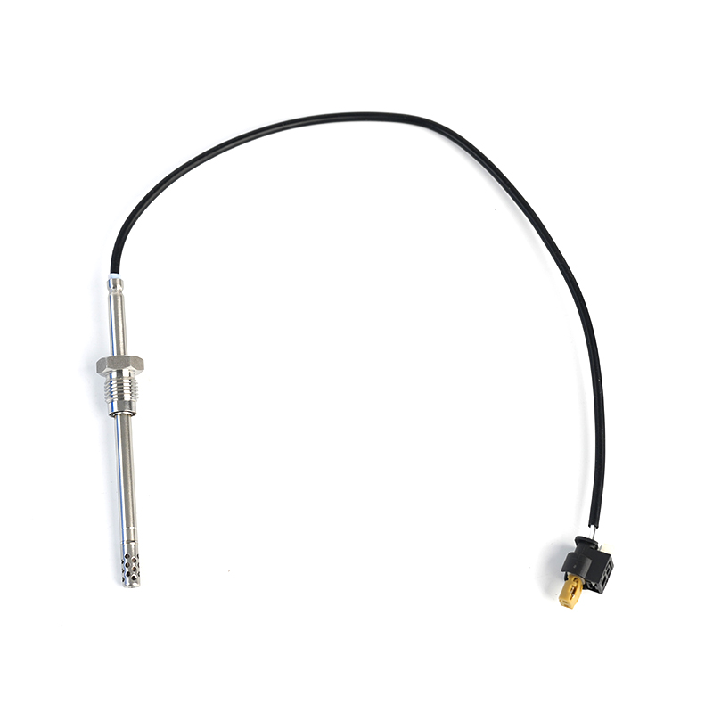
MERCEDES-BENZC-CLASS (W203) (2000/05 - 2007/08)MERCEDES-BENZC-CLASS Coupe (CL203) (2001/03 - 2011/06...
See Details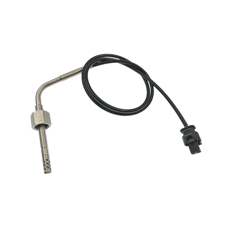
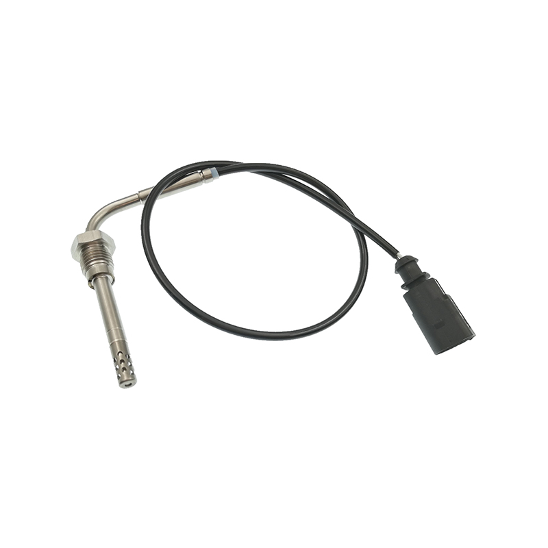
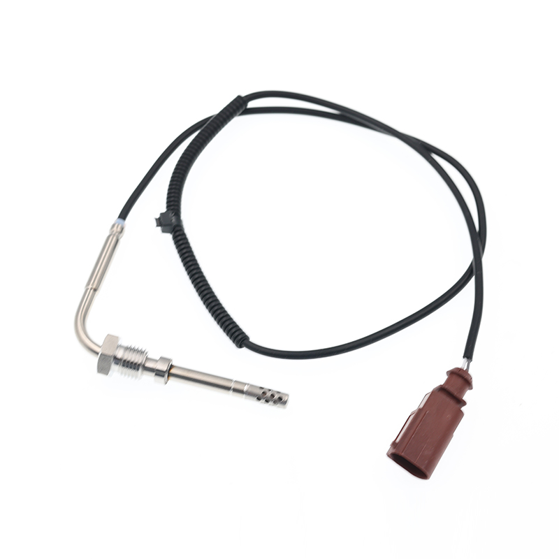
AUDIQ7 (4L) (2006/03 - 2015/08)VWTOUAREG (7LA, 7L6, 7L7) (2002/10 - 2010/05)
See Details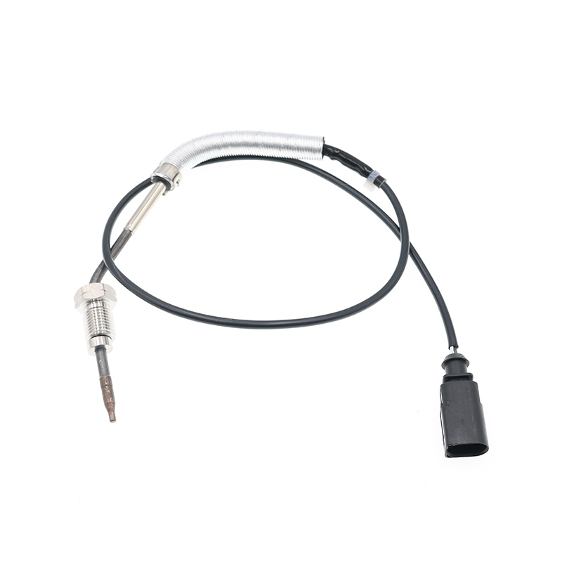
AUDIA3 (8P1) (2003/05 - 2012/08)AUDIA3 Sportback (8PA) (2004/09 - 2013/03)AUDIA4 (8EC, B7) (2004/11 ...
See Details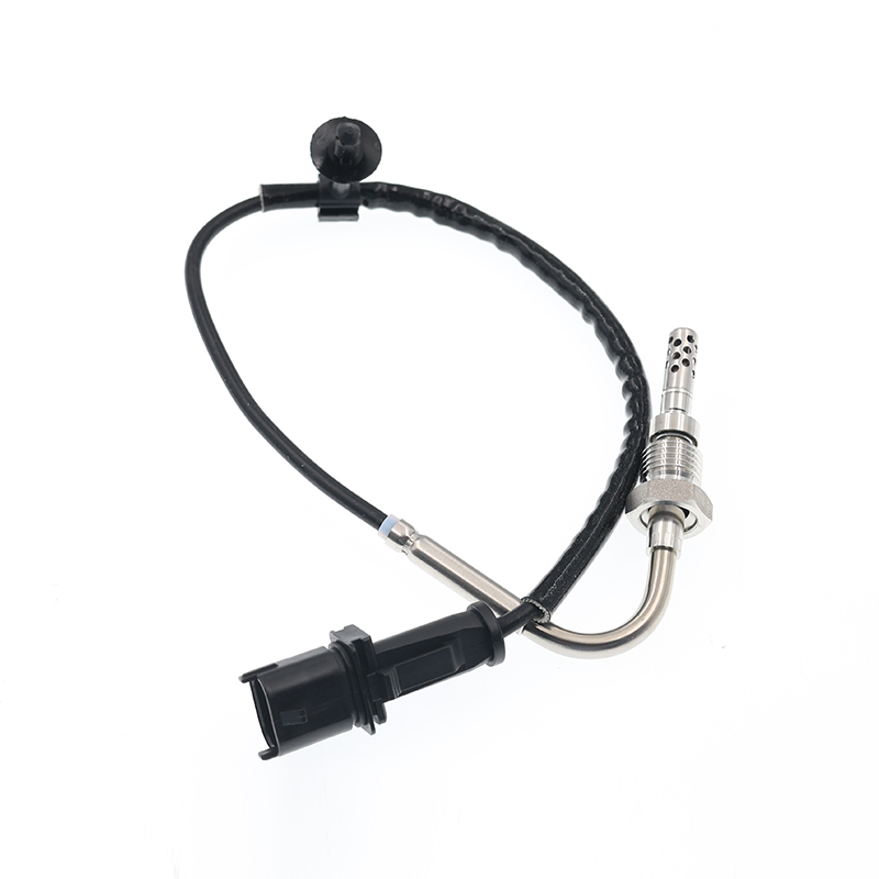
OPEL ASTRA J (2009/12 - /) OPEL ASTRA J Sports Tourer (2010/10 - /) OPEL ASTRA GTC J ...
See Details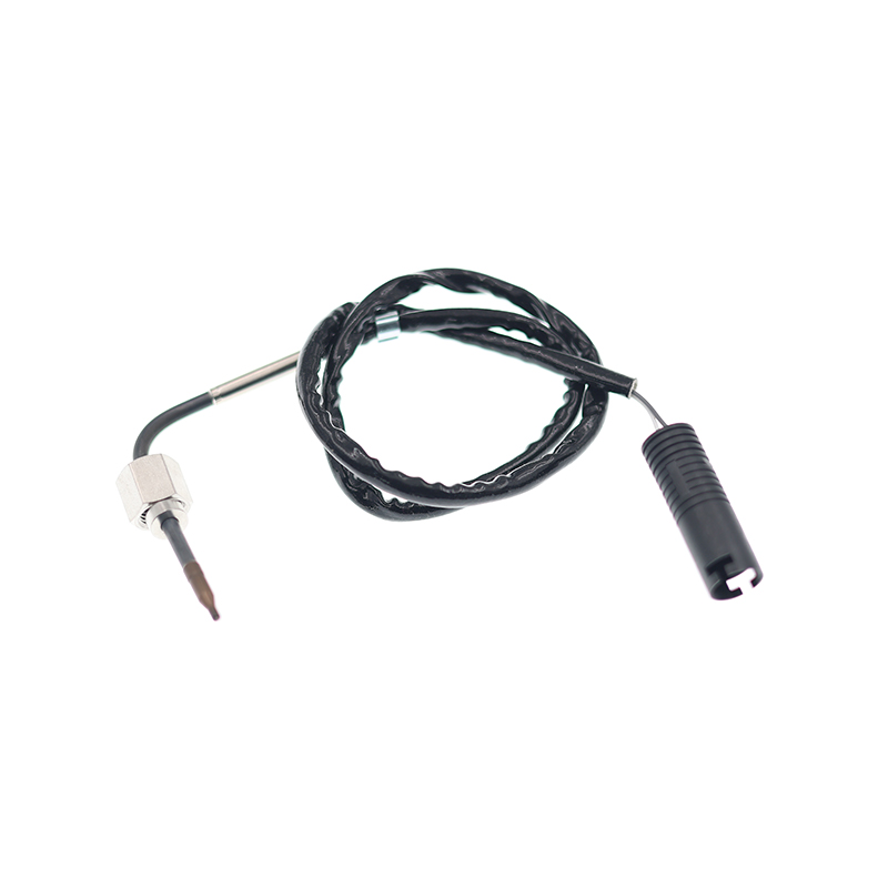
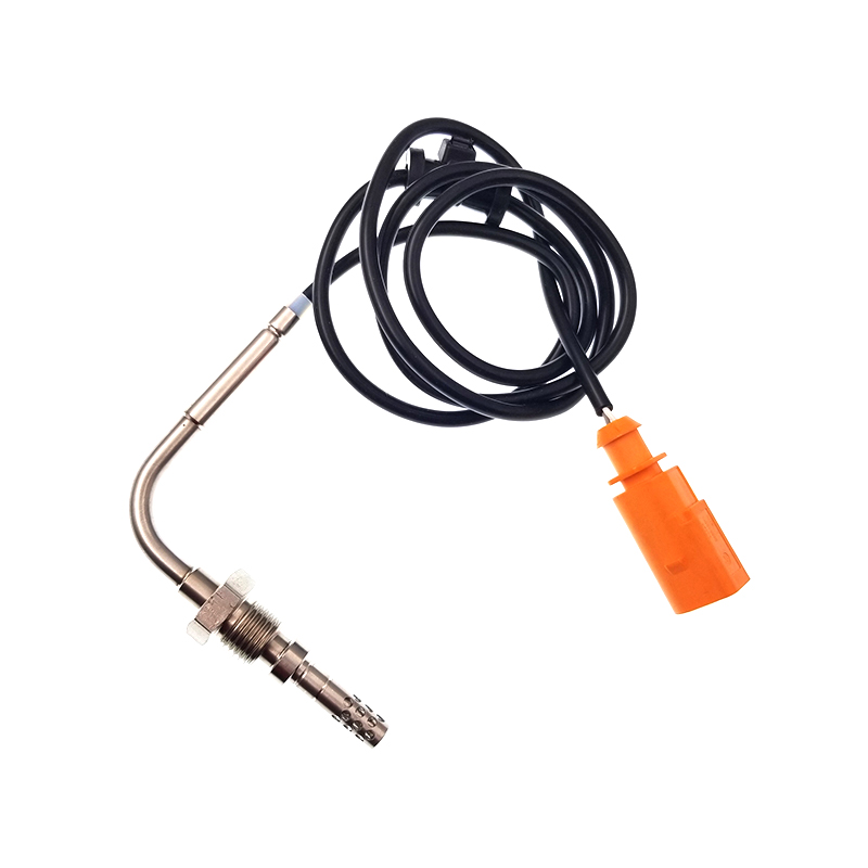
VWJETTA III (1K2) (2005/08 - 2010/10) VWGOLF VI (5K1) (2008/10 - 2013/11) VWGOLF VI Varia...
See Details
ADD: No.85 Jiuyuan Road, Economic Development Zone, Gaoyou city ,Yangzhou city ,225600 Jiangsu Province, China.
Copyright © Sook High Tech (Jiangsu) Co., Ltd. All Rights Reserved. OEM/ODM Automotive Sensor Manufacturers

