
 English
 Español
 Français
 简体中文
简体中文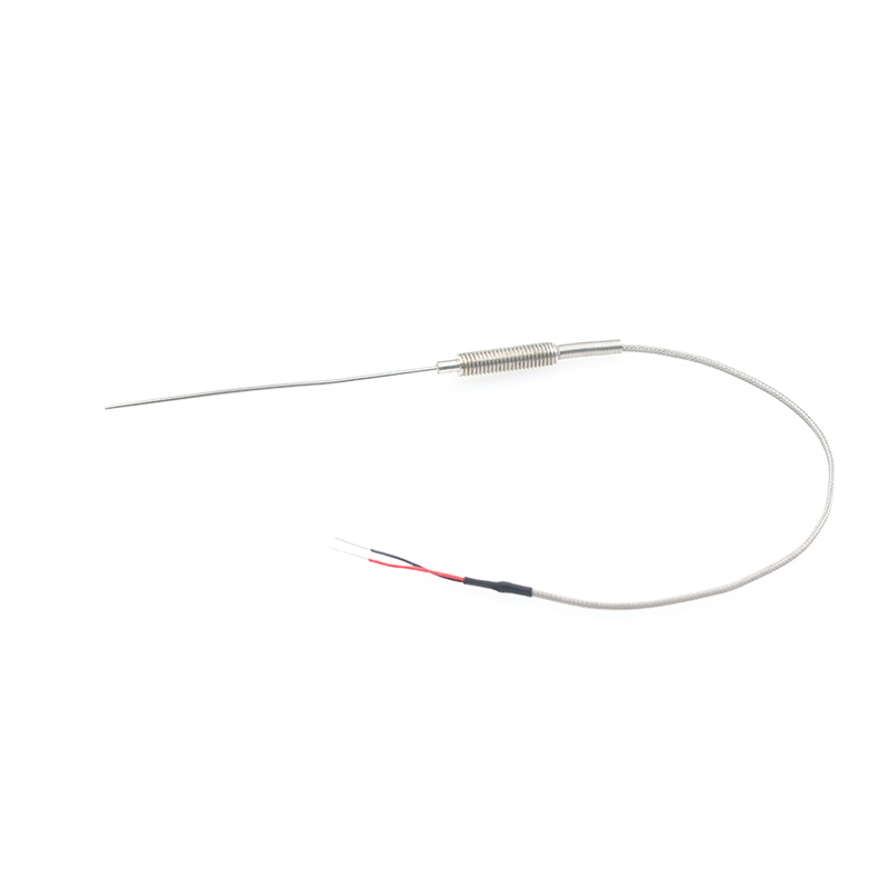
ADD: No.85 Jiuyuan Road, Economic Development Zone, Gaoyou city ,Yangzhou city ,225600 Jiangsu Province, China.
MERCEDES-BENZC-CLASS (W203) (2000/05 - 2007/08)MERCEDES-BENZC-CLASS Coupe (CL203) (2001/03 - 2011/06...
See DetailsContent
A thermocouple works because two different metals joined at one point generate a small voltage when that point is heated or cooled. The voltage is not a power source you can run a motor with; it is a signal, often only a few millivolts, that a transmitter or controller converts into a temperature reading. This makes thermocouples the default choice for exhaust gas temperature, furnace monitoring, heat-treating, and many industrial processes where fast response and high temperature limits matter more than absolute precision.
The practical consequences follow from that single principle: the junction must be insulated from ground, the second junction, called the cold junction, must be known, and the wires must match the thermocouple type. Below we walk through the physics, the hardware, the common types, cold-junction compensation, and the selection mistakes that cause most field failures.
When two dissimilar metals, such as the nickel-chromium and nickel-silicon alloys in a type K thermocouple, are joined at one end, a temperature difference between that measuring end and the other end produces an electromotive force. This is the Seebeck effect. For a type K pair, the output is roughly 41 microvolts per degree Celsius of temperature difference. That number sounds tiny, and it is. The transmitter therefore needs high input impedance and good noise rejection, because the signal is easily swamped by electrical interference.
The voltage is also not perfectly linear with temperature. Over a narrow range, a straight-line approximation may be good enough. Over a wide range, the controller must use a standard reference table or a polynomial fit. The cold end of the circuit, usually at the transmitter terminals, is part of the measurement whether you want it to be or not. If the terminal temperature changes, the reading changes with it.
The hot junction is the point that touches the process. It is often welded into a small bead and fitted inside a protective sheath. The cold junction is the point where the thermocouple wires meet the copper circuit of the instrument. A thermocouple does not measure absolute temperature at the hot junction alone; it measures the difference between the two junctions. That is why a thermocouple connected to a meter without cold-junction compensation will read incorrectly whenever the room or cabinet temperature moves.
The instrument measures a voltage difference. It does not know the hot-junction temperature unless it also knows the cold-junction temperature. Modern transmitters measure the terminal temperature with a thermistor or integrated sensor, convert that temperature into an equivalent millivolt value, add it to the measured voltage, and then linearize the result. If you run ordinary copper wire from the thermocouple to the instrument, you create a new junction at the connection point and lose the compensation the system was designed to provide.
A working thermocouple is more than two wires twisted together. Each part of the assembly affects response time, temperature limit, and service life. The main components are the thermoelements, the measuring junction, the insulation, the protective sheath, and the connector or transmitter.
Grounding is a frequent source of trouble. A grounded junction gives excellent thermal contact, but if the sheath touches an electrically live surface, the measurement circuit can pick up noise or even damage the input. An ungrounded junction costs a little response speed but often saves hours of troubleshooting.
Cold-junction compensation sounds mathematical, but the field implementation is straightforward. The goal is to make the instrument believe the cold junction is always at 0°C, even though the terminals are really sitting in a warm cabinet or a cold outdoor enclosure.
An ice bath is the classic laboratory reference for 0°C, but it is impractical for most plants. Electronic compensation is now standard. The one rule that never changes is that extension wire and terminal blocks must match the thermocouple type. Copper wire cannot carry a thermocouple signal without creating a new, uncompensated junction.
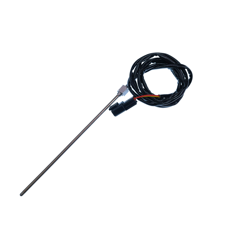 Automotive Thermocouple EGT Sensors for Exhaust Gas TemperatureChoose K, N, or E thermocouple EGT sensors with mineral-insulated sheaths, armored probes, and part numbers for Mack, Scania, Cummins, John Deere, Volvo, and HINO.View Product →
Most thermocouple problems are not caused by the sensor itself. They come from wrong wiring, poor installation, or missing compensation. The table below pairs the most frequent field complaints with practical fixes.
| Problem | What to do |
|---|---|
| Wrong thermocouple type selected | Match the transmitter, extension wire, and sensor to the same type and color code. |
| Reversed polarity | Check terminal markings and the thermocouple wire color code before tightening. |
| Grounded junction with a ground loop | Use an ungrounded junction or an isolated input to break the loop. |
| Cold junction not compensated | Replace direct copper wiring with a transmitter that has cold-junction compensation. |
| Decalibration from vibration or contamination | Replace the sensor and choose a sheath material that survives the atmosphere. |
A quick check with a known temperature source often reveals whether the error is in the sensor, the wiring, or the transmitter configuration.
Start with the process temperature, not the thermocouple type. Then add the atmosphere, required accuracy, response time, and mechanical protection. A type K sensor in a stainless steel sheath may be perfect for a flue gas duct, but it can fail quickly in a reducing atmosphere or in contact with certain molten metals.
For replacement parts, custom assemblies, or a review of an existing installation, the thermocouple EGT sensor article and the company’s manufacturing background provide useful context for automotive and industrial applications.
A thermocouple is a simple device with a demanding measurement chain. Two dissimilar metals create a voltage, but that voltage only becomes a reliable temperature reading when the cold junction is compensated, the wires match the type, and the sheath suits the process. If you keep those three conditions in view, most thermocouple installations will be accurate, repeatable, and long-lived.
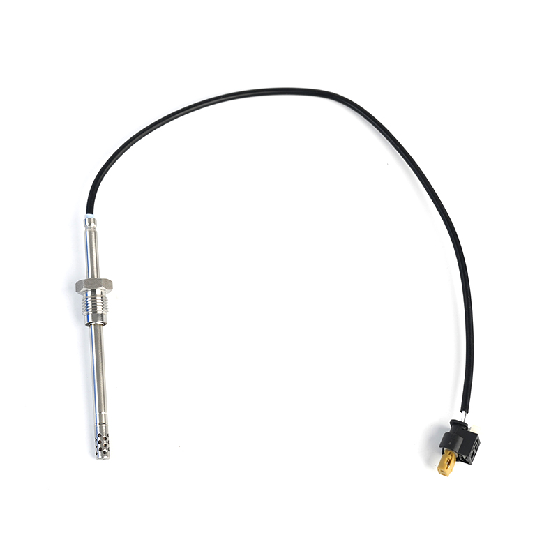
MERCEDES-BENZC-CLASS (W203) (2000/05 - 2007/08)MERCEDES-BENZC-CLASS Coupe (CL203) (2001/03 - 2011/06...
See Details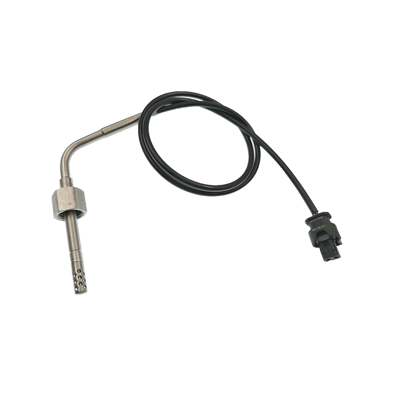
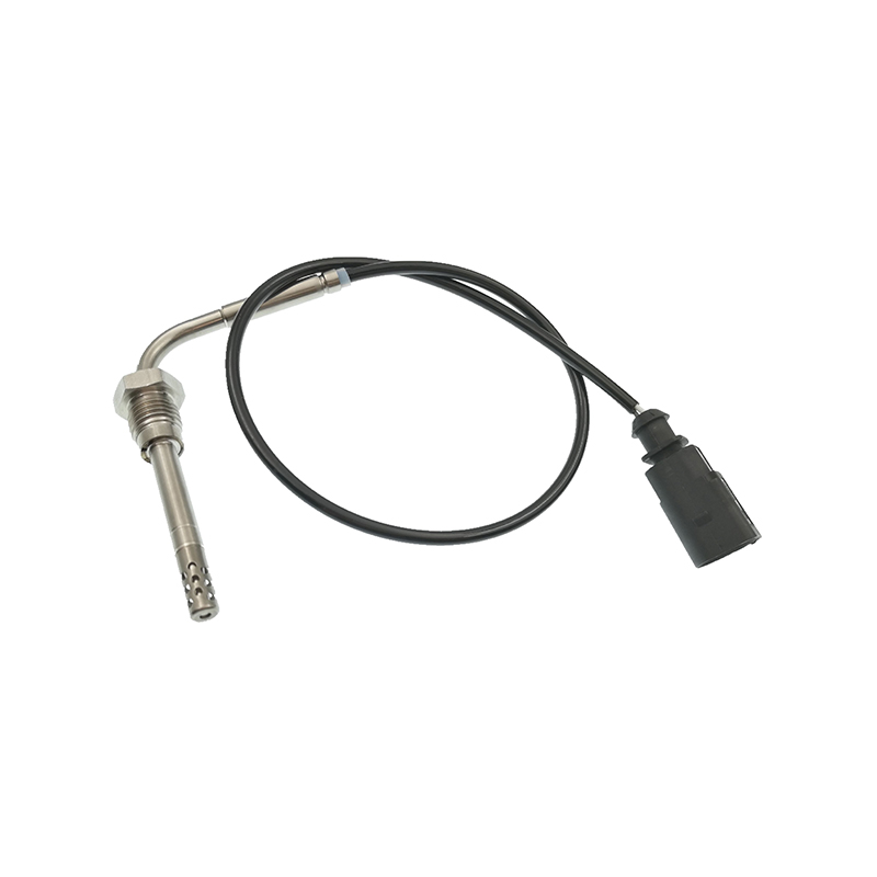
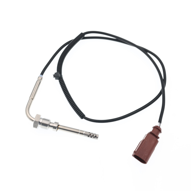
AUDIQ7 (4L) (2006/03 - 2015/08)VWTOUAREG (7LA, 7L6, 7L7) (2002/10 - 2010/05)
See Details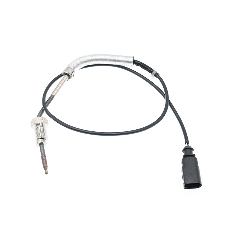
AUDIA3 (8P1) (2003/05 - 2012/08)AUDIA3 Sportback (8PA) (2004/09 - 2013/03)AUDIA4 (8EC, B7) (2004/11 ...
See Details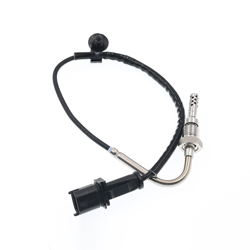
OPEL ASTRA J (2009/12 - /) OPEL ASTRA J Sports Tourer (2010/10 - /) OPEL ASTRA GTC J ...
See Details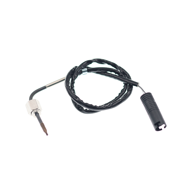
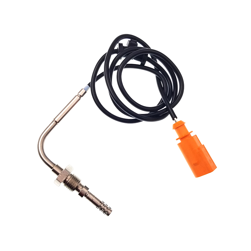
VWJETTA III (1K2) (2005/08 - 2010/10) VWGOLF VI (5K1) (2008/10 - 2013/11) VWGOLF VI Varia...
See Details
ADD: No.85 Jiuyuan Road, Economic Development Zone, Gaoyou city ,Yangzhou city ,225600 Jiangsu Province, China.
Copyright © Sook High Tech (Jiangsu) Co., Ltd. All Rights Reserved. OEM/ODM Automotive Sensor Manufacturers

