
 English
 Español
 Français

 简体中文
ADD: No.85 Jiuyuan Road, Economic Development Zone, Gaoyou city ,Yangzhou city ,225600 Jiangsu Province, China.
MERCEDES-BENZC-CLASS (W203) (2000/05 - 2007/08)MERCEDES-BENZC-CLASS Coupe (CL203) (2001/03 - 2011/06...
See DetailsContent
You are designing the DC-bus current measurement for a 1.2 kV motor-drive stage. The components inside the cabinet sit near the busbar, and the sensor input does not sit at ground potential; it sits at the full bus voltage. Of the three current sensing options on your desk, only two can measure direct current, and one of those options will change its accuracy with temperature more than you expect.
The conclusion comes before the component comparison: write down four numbers first (maximum common-mode voltage, current range, bandwidth, and acceptable error over temperature). The sensor with the best datasheet accuracy is not the best sensor if its common-mode limit or thermal drift forces a system redesign later.
Common-mode voltage is the voltage that both sensing terminals see with respect to the local ground. On a floating high-side shunt, that voltage equals the bus potential. On a Hall-based sensor, the measurement is taken from the magnetic field, so the common-mode limit is set by the insulation of the sensor housing and the physical spacing inside the cabinet.
The practical range differs strongly from sensor type to sensor type: an isolated amplifier with a shunt resistor can be rated for 100 V to 1200 V common-mode, while a closed-loop Hall current sensor mounted on a busbar depends on its housing insulation and the surrounding layout. When the common-mode voltage exceeds the sensing element rating, the output saturates, drifts, or fails permanently.
Treat common-mode voltage as a gate criterion, not a preference. Apply the same reasoning to the supply: an isolated amplifier needs a floating supply, and that supply must have the same isolation rating as the signal path.
Where you place the sense element determines the common-mode stress and the quality of the measured signal. High-side sensing places the shunt or sensor in the live line and keeps the load reference intact. Low-side sensing is simpler, but it introduces ground noise and may miss load faults.
| Aspect | High-Side | Low-Side |
|---|---|---|
| Common-mode voltage | Full bus voltage at the sense element | Near ground |
| Noise coupling | Good rejection of bus-side noise | PCB ground noise enters the reading |
| Load fault detection | Detects ground faults on the load | Misses faults that short the load to ground |
| Circuit complexity | Needs isolated supply or isolated amplifier | Simple low-voltage op-amp possible |
| Typical accuracy | 0.5% to 2% | 1% to 3% |
Table: high-side vs low-side placement trade-offs for high-voltage current sensing.
Bandwidth defines which part of the current signal you will correctly reproduce. A closed-loop Hall sensor may cover direct current up to a few hundred kilohertz; an isolated shunt amplifier can go higher in frequency but adds more noise; a current transformer simply cannot carry DC. Use the waveform, not the datasheet headline, as the deciding input.
A shunt resistor with a temperature coefficient of 50 ppm/°C produces a larger error over an 80 °C swing than most engineers expect. Hall sensors have their own thermal drift from the core and the electronics. The measuring element, the amplifier, and the surrounding PCB all contribute to the final error.
The practical consequence is simple: if you specify accuracy at 25 °C only, the field performance at 85 °C can exceed your protection threshold. That is why a temperature channel is not an extra option; it is part of the current-sensing error budget.
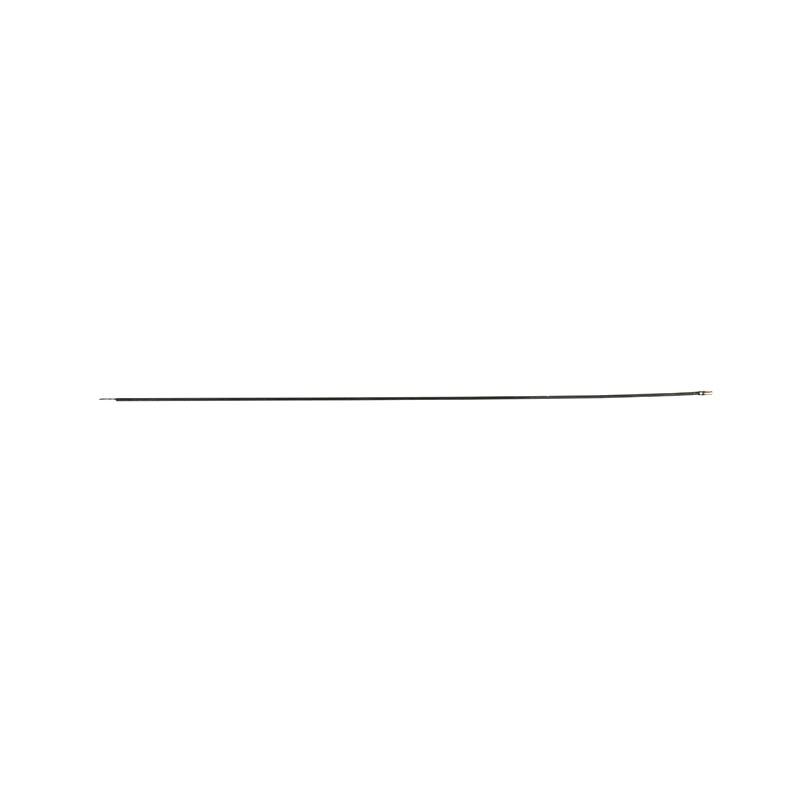 Thermal Resistance Temperature Sensor ManufacturersA thermal resistance temperature sensor is a kind of sensor thermometer that uses the principle that the resistance value of a conductor or semiconductor changes with ...View Product →
A sensor that passes a 2.5 kVRMS dielectric test for one minute can have a significantly lower continuous working voltage. Datasheets list both numbers for a reason. In addition, the isolation rating of the sensor is only one part of the system; the creepage distance on the PCB and the air clearance around the sensor must match the working voltage, pollution degree, and material group of the application.
Follow the logic of IEC 60664-1 when you define spacing. For altitudes above 2000 m, derate the clearance requirement further. If the sensor sits in a cabinet, add physical barriers when clearance is tight, and ask the component manufacturer for the isolation test report instead of accepting a printed rating at face value.
Include isolation in the purchasing record. A datasheet value without a test certificate is not enough for a safety-relevant high-voltage design.
In a high-voltage cabinet, the current sensor does not work alone. Busbars heat, terminations age, condensation forms on cold surfaces, and oil-filled equipment slowly loses level. A reliable sensing design includes the surrounding protection: a temperature readout on the hot joints, an armored heater to keep internal air above the dew point, and a level sensor to detect oil loss in conservator tanks.
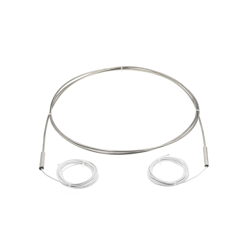 Armored heaterProduct Model: 230V 1500WView Product →
SOOK High Tech's production facility builds thermistors, thermocouples, armored heaters, mineral-insulated cables, and liquid-level sensors in-house. When the components around the current sensor come from one engineering team, layout approval, qualification testing, and delivery scheduling become simpler.
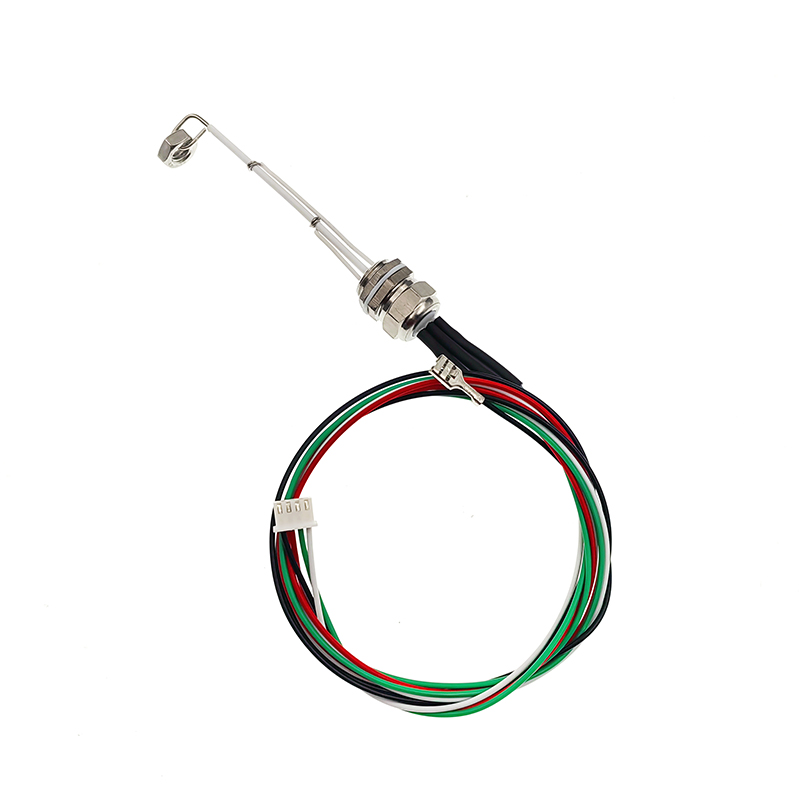 Water level sensorProduct item No.: SKT-2570View Product →
| Common Mistake | Consequence | Recommended Practice |
|---|---|---|
| Measuring current without monitoring busbar temperature | Loose joints stay unnoticed until they overheat and fail | Mount a thermistor or thermocouple on the hot joint and alarm on the trend |
| Ignoring humidity in an outdoor-rated cabinet | Condensation reduces insulation strength and can cause flashover | Add an armored heater and keep internal temperature above the dew point |
| Placing the current sensor next to a heat source | Thermal drift degrades accuracy exactly when current is high | Separate the sensor from the heat source or include the temperature in the error budget |
| Forgetting oil level in transformer-type enclosures | Slow leaks lower the dielectric level and lead to internal discharge | Use a liquid-level sensor in the conservator and integrate the signal into the monitoring scope |
Table: recurring system-level mistakes in high-voltage current sensing installations.
Start with four numbers: maximum common-mode voltage, current range, bandwidth, and worst-case accuracy over temperature. Add the isolation rating, the thermal budget, and the approval documents. These constraints will narrow the sensing principle faster than any brand comparison.
When surrounding components like temperature sensors, heaters, cables, and liquid-level sensors are part of the same design review, specification errors become visible earlier. Contact SOOK's engineering team when your application needs temperature or environmental sensing around a high-voltage current measurement, and they will review the layout with production constraints in mind.
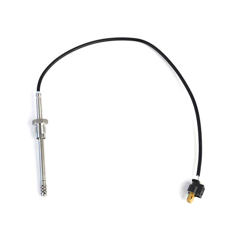
MERCEDES-BENZC-CLASS (W203) (2000/05 - 2007/08)MERCEDES-BENZC-CLASS Coupe (CL203) (2001/03 - 2011/06...
See Details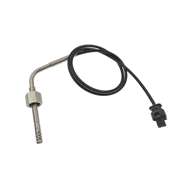
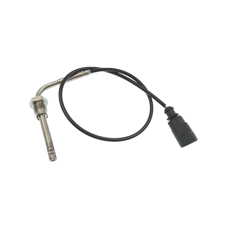
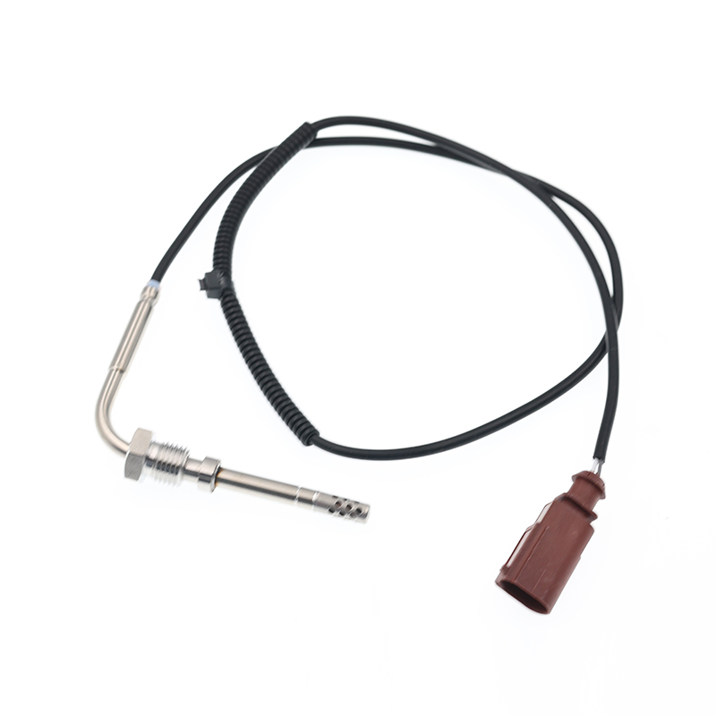
AUDIQ7 (4L) (2006/03 - 2015/08)VWTOUAREG (7LA, 7L6, 7L7) (2002/10 - 2010/05)
See Details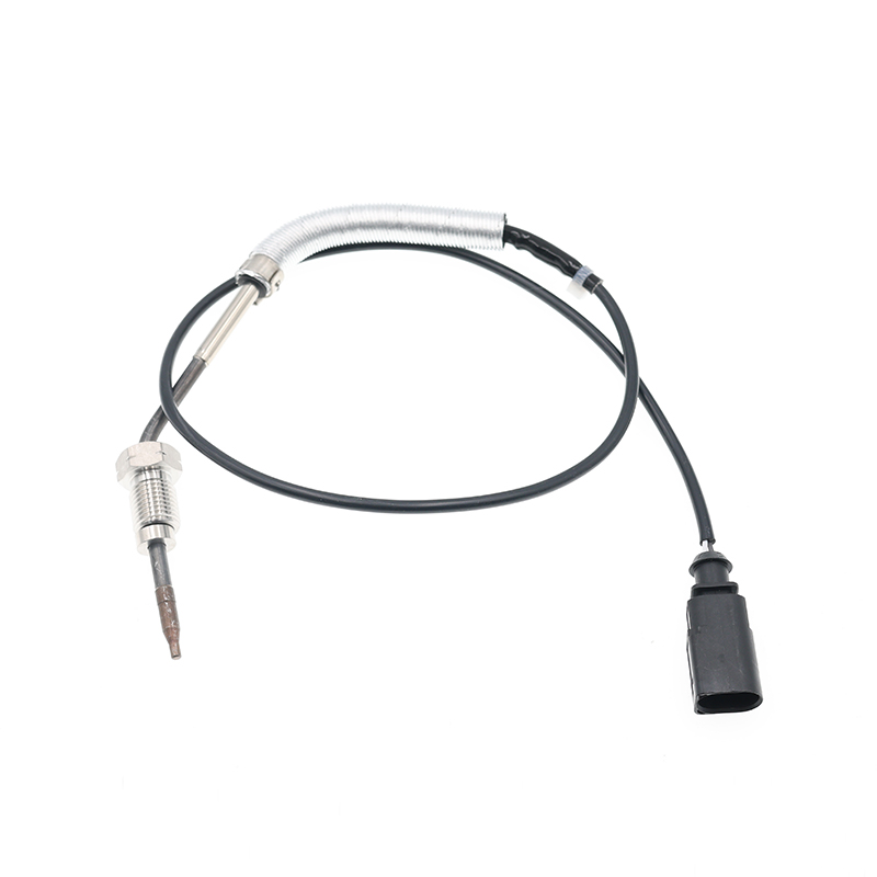
AUDIA3 (8P1) (2003/05 - 2012/08)AUDIA3 Sportback (8PA) (2004/09 - 2013/03)AUDIA4 (8EC, B7) (2004/11 ...
See Details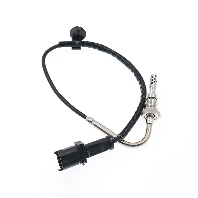
OPEL ASTRA J (2009/12 - /) OPEL ASTRA J Sports Tourer (2010/10 - /) OPEL ASTRA GTC J ...
See Details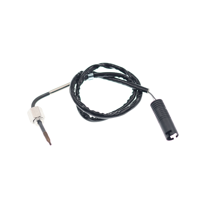
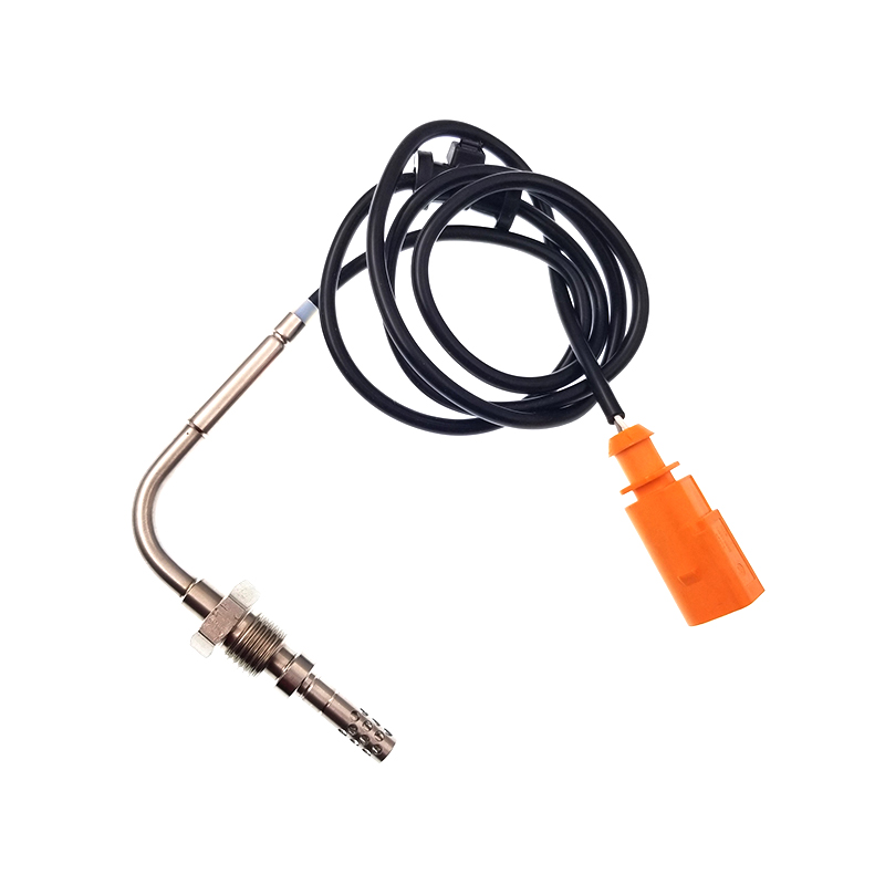
VWJETTA III (1K2) (2005/08 - 2010/10) VWGOLF VI (5K1) (2008/10 - 2013/11) VWGOLF VI Varia...
See Details
ADD: No.85 Jiuyuan Road, Economic Development Zone, Gaoyou city ,Yangzhou city ,225600 Jiangsu Province, China.
Copyright © Sook High Tech (Jiangsu) Co., Ltd. All Rights Reserved. OEM/ODM Automotive Sensor Manufacturers

