
 English
 Español
 Français

 简体中文
ADD: No.85 Jiuyuan Road, Economic Development Zone, Gaoyou city ,Yangzhou city ,225600 Jiangsu Province, China.
MERCEDES-BENZC-CLASS (W203) (2000/05 - 2007/08)MERCEDES-BENZC-CLASS Coupe (CL203) (2001/03 - 2011/06...
See DetailsContent
A field engineer watches an industrial heating line log a slow drop in current over three shifts. Nothing trips, no alarm sounds, but the temperature controller starts struggling to hold its setpoint. The component that makes this slow failure visible is a current transducer sensor — a device that converts a live current into a small, isolated output signal that a PLC, data logger, or building controller can read safely.
The conclusion that saves the most troubleshooting time is straightforward: choose the measuring principle that matches the signal type — DC, AC, or pulsed — and the output format that the control system actually accepts. Accuracy class, aperture size, and isolation rating all follow from those two decisions.
A current transducer sensor measures the current flowing through a conductor without interrupting the circuit. It converts the measured current into a proportional, galvanically isolated output — typically a voltage such as 0–10 V, a current such as 4–20 mA, or a digital signal such as CAN. That isolation is what makes the sensor safe to connect directly to PLC inputs and data acquisition terminals in the same cabinet as the power circuit.
Two Hall-effect topologies dominate modern designs. In an open-loop transducer, the Hall element output is amplified directly; this is the compact and cost-effective choice for most monitoring duties. In a closed-loop, or compensated, transducer, a secondary winding actively cancels the magnetic flux, yielding better accuracy and thermal stability at the cost of higher power consumption and a larger package. For AC-only measurement, a current transformer uses induction rather than a Hall element and cannot measure DC at all.
"Current sensor" is the umbrella term for any component that measures current. A current transducer is specifically a sensor that produces an isolated, standardized output signal, while a current transformer is an inductive device limited to alternating current.
| Comparison point | Current transducer (Hall effect) | Current transformer | Shunt resistor |
|---|---|---|---|
| Measures DC | Yes | No — AC only | Yes |
| Measures AC | Yes | Yes | Yes |
| Typical output | 0–10 V, 4–20 mA, CAN | Scaled AC current, e.g. 5 A or 1 A secondary | Small millivolt drop |
| Galvanic isolation | Built in | Intrinsic | None — direct connection |
| Typical accuracy | 0.1%–1.0% | 0.5%–1.0% (class-dependent) | 0.5%–2.0% (temperature-dependent) |
| Typical cost | Moderate to high | Low to moderate | Low |
Table 1 — Typical differences between the three most common current-measuring components. "Current sensor" is the umbrella term; a current transducer is a Hall-effect sensor with an isolated, standardized output.
Three numbers decide whether a current transducer will work reliably in your installation: the rated primary current, the accuracy class, and the working isolation voltage. A fourth — the specified bandwidth — matters as soon as variable-frequency drives or switched-mode power supplies are involved.
For most HVAC and motor-protection duties, 1.0% accuracy is enough; battery testing, power analysis, and energy metering call for 0.1%–0.5%.
Real transducers also carry imperfections: offset drift, temperature coefficients, and limited frequency response change with ambient heat, so the accuracy stated at 25 °C is not the whole story. Check the full operating temperature range — commonly -40 °C to +85 °C for industrial units — and verify the isolation rating against the system's phase-to-ground voltage before installation. Output settling time also matters in fast-switching circuits, where a slow transducer can mask short current spikes.
Apply the same five checks on every project, whether the transducer goes into a motor panel, a heater cabinet, or a battery test bench.
The failures that reach the field are rarely about the transducer brand. They come from mismatches between the datasheet and the real installation.
| Common mistake | What to check instead |
|---|---|
| Specifying a 50/60 Hz transducer for a variable-frequency drive | Check the bandwidth specification; VFD circuits need a transducer rated for the carrier frequency, not the line frequency. |
| Using a shunt resistor where galvanic isolation is required | Choose a Hall-effect transducer or current transformer with an isolation voltage rating that covers the system's phase-to-ground voltage. |
| Judging accuracy only at 25 °C | Compare the accuracy class over the full operating temperature range, because offset drift changes the real error at high ambient temperatures. |
| Selecting an output the controller cannot read | Confirm the analog or digital output — 4–20 mA, 0–10 V, or CAN — and match the transducer supply voltage to the panel power source. |
Table 2 — Frequent specification errors and the checks that prevent them.
A current transducer rarely works alone. In a heated mould or a commercial oven, the transducer tracks the current drawn by each heating element while a thermocouple measures the actual process temperature; both signals feed the same controller.
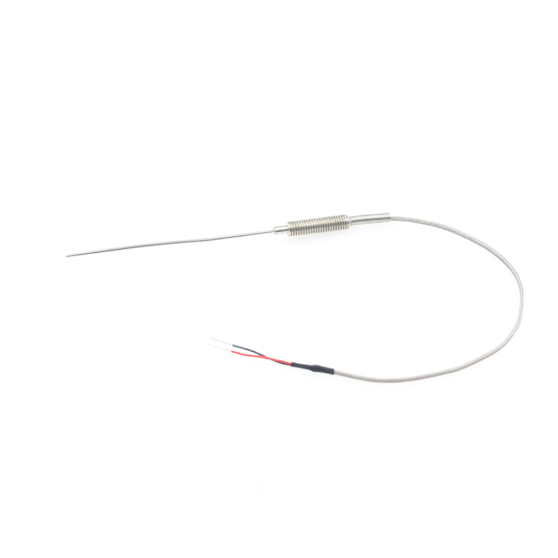 Thermocouple Temperature Sensors for Industrial Process MonitoringThermocouples generate voltage from the Seebeck effect to measure temperature, complementing current transducers in heating applications where both signals feed the same controller. This position highlights a reliable temperature sensing option.View Product →
On the signal side, the transducer output is only as reliable as its wiring. Shielded and mechanically protected cables prevent the millivolt or milliampere signal from picking up interference from motor drives; in hot plant areas, stainless steel sheathed signal cables survive temperatures that damage PVC insulation.
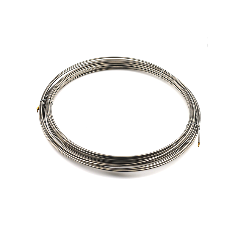 Stainless Steel Signal Cables for Harsh Environment WiringThese cables use a 316L stainless steel sheath and copper conductors to protect millivolt signals from interference and heat. Relevant where transducer wiring must survive high temperatures and corrosion in industrial plants.View Product →
In battery and charging applications, Hall-effect transducers measure charge and discharge current in EVs, forklifts, and UPS equipment. In motor control, a transducer detects overload and phase loss, while a separate temperature sensor protects the winding. These are the combinations where component selection decides long-term reliability.
SOOK, a sensor manufacturer with two in-house factories and a yearly capacity of 600,000 sensors, supplies the industrial temperature sensors, cables, and heater elements that are specified alongside current-measuring components. You can compare the full product range on the product overview page, or inspect the production lines on the factory equipment page.
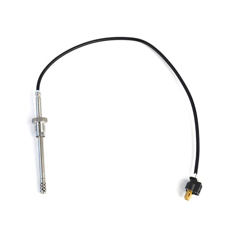
MERCEDES-BENZC-CLASS (W203) (2000/05 - 2007/08)MERCEDES-BENZC-CLASS Coupe (CL203) (2001/03 - 2011/06...
See Details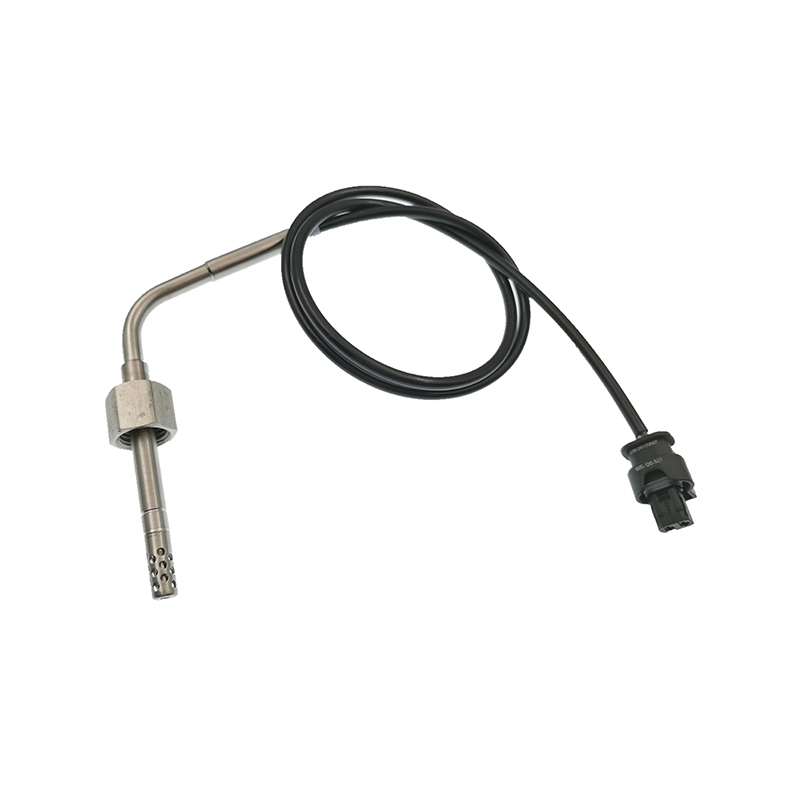
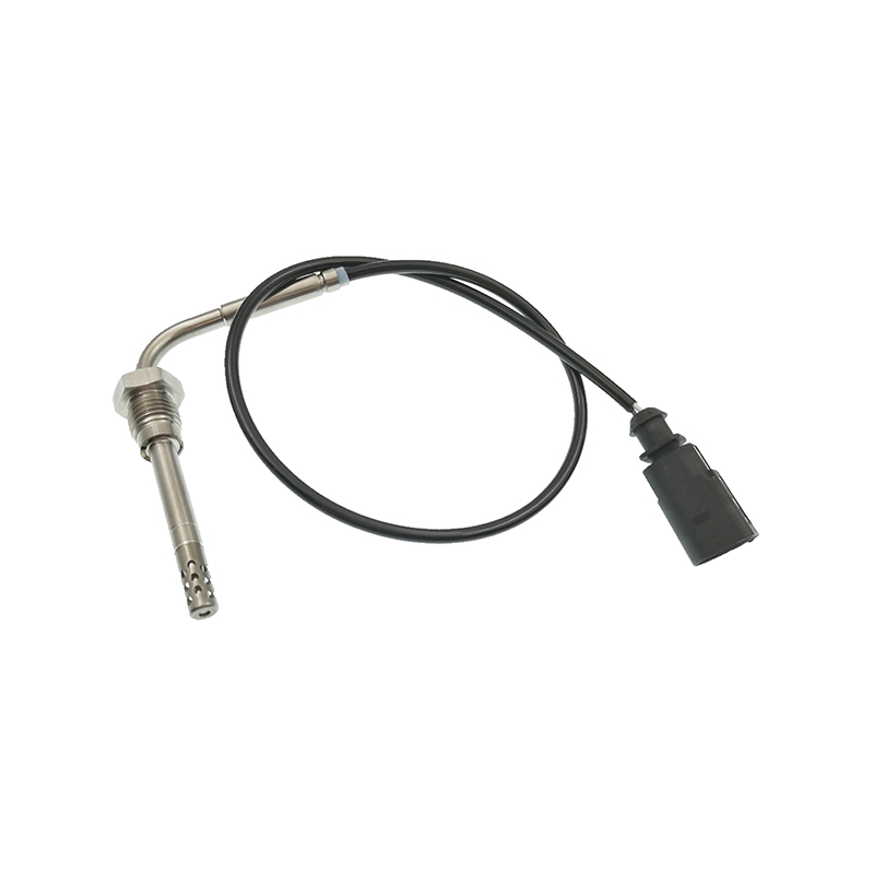
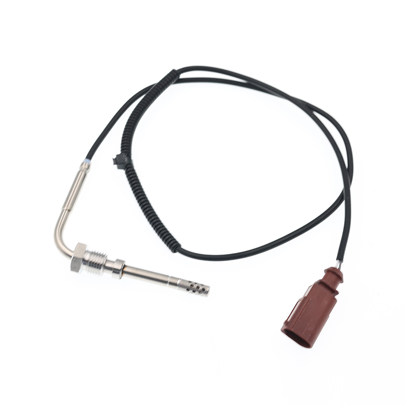
AUDIQ7 (4L) (2006/03 - 2015/08)VWTOUAREG (7LA, 7L6, 7L7) (2002/10 - 2010/05)
See Details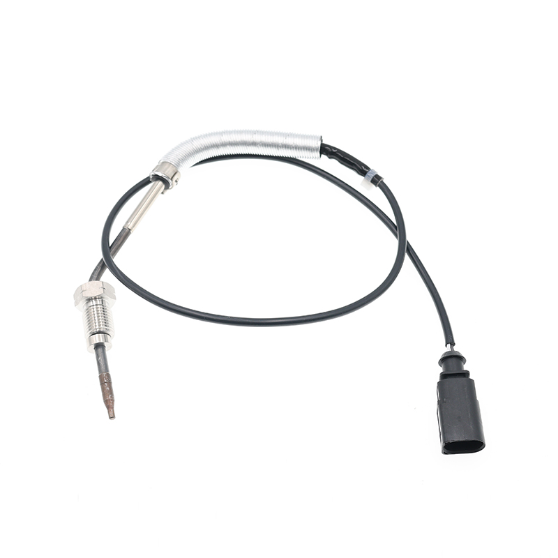
AUDIA3 (8P1) (2003/05 - 2012/08)AUDIA3 Sportback (8PA) (2004/09 - 2013/03)AUDIA4 (8EC, B7) (2004/11 ...
See Details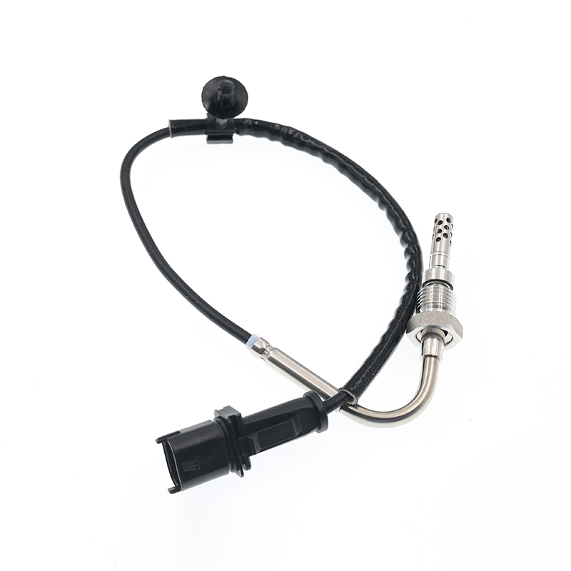
OPEL ASTRA J (2009/12 - /) OPEL ASTRA J Sports Tourer (2010/10 - /) OPEL ASTRA GTC J ...
See Details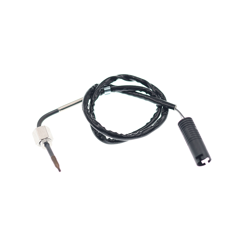
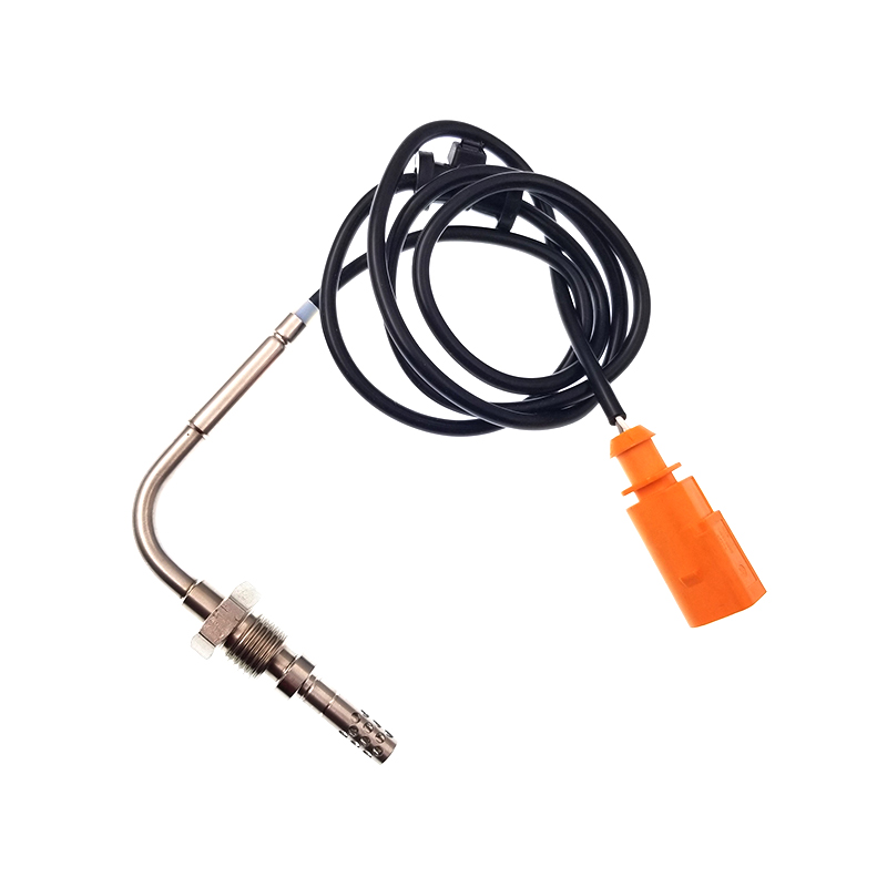
VWJETTA III (1K2) (2005/08 - 2010/10) VWGOLF VI (5K1) (2008/10 - 2013/11) VWGOLF VI Varia...
See Details
ADD: No.85 Jiuyuan Road, Economic Development Zone, Gaoyou city ,Yangzhou city ,225600 Jiangsu Province, China.
Copyright © Sook High Tech (Jiangsu) Co., Ltd. All Rights Reserved. OEM/ODM Automotive Sensor Manufacturers

