
 English
 Español
 Français

 简体中文
ADD: No.85 Jiuyuan Road, Economic Development Zone, Gaoyou city ,Yangzhou city ,225600 Jiangsu Province, China.
MERCEDES-BENZC-CLASS (W203) (2000/05 - 2007/08)MERCEDES-BENZC-CLASS Coupe (CL203) (2001/03 - 2011/06...
See DetailsContent
A 2016 compact SUV arrives with a fresh ABS sensor, a clean scan-tool report, and the same intermittent wheel-speed code. The new part is not the problem; the circuit is. A terminal with 0.4 V of drop or a ground strap that only fails under load can make a healthy sensor look defective. That is why automotive electrical testing should start with the current path, not with the component at the end of the harness.
The working conclusion: test the circuit under load, prove the ground, then judge the sensor. An open-circuit voltmeter check is only a starting point because it will pass a circuit that fails the moment an ABS motor or heater draws current. A repeatable sequence uses voltage-drop measurements, back-probing at the connector, and a signal check with the system awake. That order keeps a wiring fault from becoming a parts-swapping habit.
Match the test to the question before choosing a tool. The comparison below is a practical starting point for 12 V and low-voltage sensor circuits; it does not replace the vehicle-specific procedure.
| Test | Question it answers | Reading worth investigating | Main limitation |
|---|---|---|---|
| Loaded voltage drop | Is the path efficient while current flows? | More than 0.1 V at one connection; more than 0.5 V across a 12 V circuit | Does not validate signal quality |
| Back-probe at connector | Is voltage present with the circuit connected? | Feed more than 0.3 V below battery voltage | Probe size can spread terminals |
| Resistance check | Is an unpowered leg open or shorted? | Outside specification, or changes when the loom is wiggled | Misleading on electronic sensors |
| Waveform or scan data | Is the signal credible while running? | Dropouts, rounded edges, missing pulses | Needs a known-good comparison |
Use the loaded voltage-drop result as the first gate: a circuit that passes unloaded but fails loaded is still a fault.
When the harness passes but the wheel-speed signal disappears, a known-good ABS sensor is the faster comparison. Match the OE number and connector style before installing it.
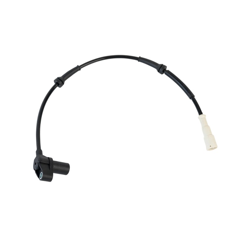 Renault Clio II and Symbol ABS Sensor 0265006383Inductive ABS sensor with 450 mm cable for listed Renault Clio II and Symbol applications; verify OE reference and connector before comparison.View Product →
0.1 V is the usual pass line for a single loaded connection — treat 0.5 V across a 12 V circuit as a warning, not a normal reading.
These values are field rules of thumb, not universal specifications. Manufacturer data wins when it is available. On a 12 V feed, a single loaded connection above 0.1 V deserves attention. A total circuit drop above 0.5 V is a warning sign. For sensor heaters, resistance changes with temperature, so compare hot and cold values against the procedure rather than trusting one number.
Keep a fused lead and a high-impedance meter on the bench, and treat a test light as a power-check tool rather than a signal probe. Back-probe only cavities that are designed for it, and reseal every connector after probing. A loose terminal created during diagnosis can become the next comeback.
On SCR-equipped diesels, NOx sensor heater and signal faults often mimic each other. Confirm heater supply, ground, and scan data before replacing the sensor. If the circuit is proven and the response is still lazy, compare the channel with a known-good NOx sensor and verify the OE reference.
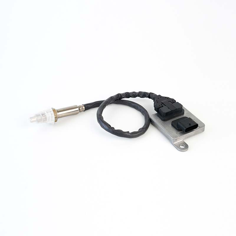 BMW NOx Sensor 11787587130 with 400 mm Cable12V NOx sensor with 400 mm cable and BMW application; compare heater and signal data against a known-good unit before replacement.View Product →
Write down before-and-after readings. A voltage-drop number that is only remembered as “looked fine” cannot support a warranty decision or help the next technician.
| Mistake | Better move |
|---|---|
| Probing through terminal insulation | Use a proper back-probe and reseal the cavity. |
| Testing resistance on a live circuit | Isolate power and follow the manufacturer's procedure. |
| Accepting an unloaded voltage reading | Load the circuit and repeat the voltage-drop test. |
| Replacing a sensor before checking ground | Prove the ground side under load; repair straps and terminals. |
| Using a test light on signal wires | Use a high-impedance meter or scope; a test light can damage drivers. |
The goal is not more tests; it is a test order that tells you when to stop replacing parts.
For exhaust-temperature circuits, confirm whether the vehicle uses an NTC, PTC, or thermocouple EGT sensor. The wrong curve can fit the connector but not the calibration.
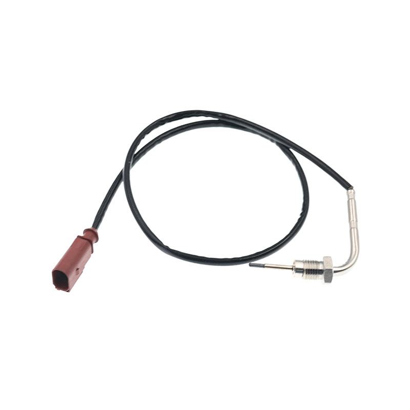 NTC EGT Sensor 03L906088BH for VW Group ModelsNTC exhaust-temperature sensor with 90-degree connector, M14x1.5 thread, and 660 mm cable; confirm the vehicle's sensor curve and fitment.View Product →
Never back-probe hybrid high-voltage cables, airbag squibs, or pyrotechnic circuits. Use fused leads, keep the meter on the correct range before connecting, and secure test leads away from fans, belts, and exhaust parts. A momentary short during probing can turn a diagnostic job into a module replacement.
A test that passes cold but fails hot needs a controlled heat soak, not a longer road test. Likewise, a circuit that passes with the connector unplugged but fails under load has told you where to look. Treat those conditions as part of the test plan.
If you are building a replacement-sensor programme, check the supplier's process discipline as carefully as the part number. SOOK's company background and factory equipment page are useful starting points for a supplier review, but the final decision should still rest on test data for the exact circuit and calibration.
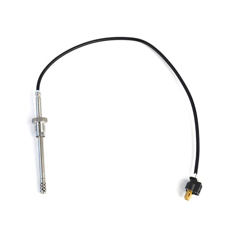
MERCEDES-BENZC-CLASS (W203) (2000/05 - 2007/08)MERCEDES-BENZC-CLASS Coupe (CL203) (2001/03 - 2011/06...
See Details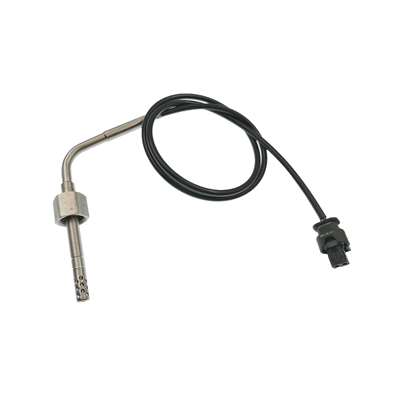
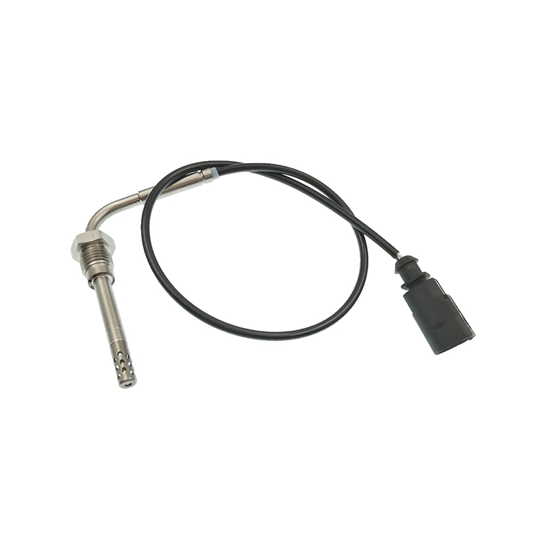
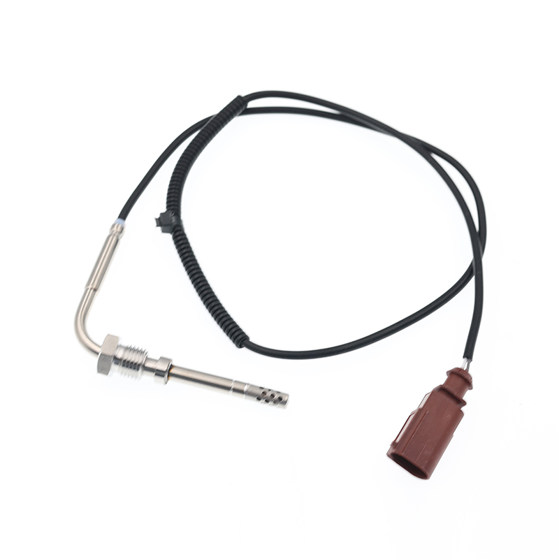
AUDIQ7 (4L) (2006/03 - 2015/08)VWTOUAREG (7LA, 7L6, 7L7) (2002/10 - 2010/05)
See Details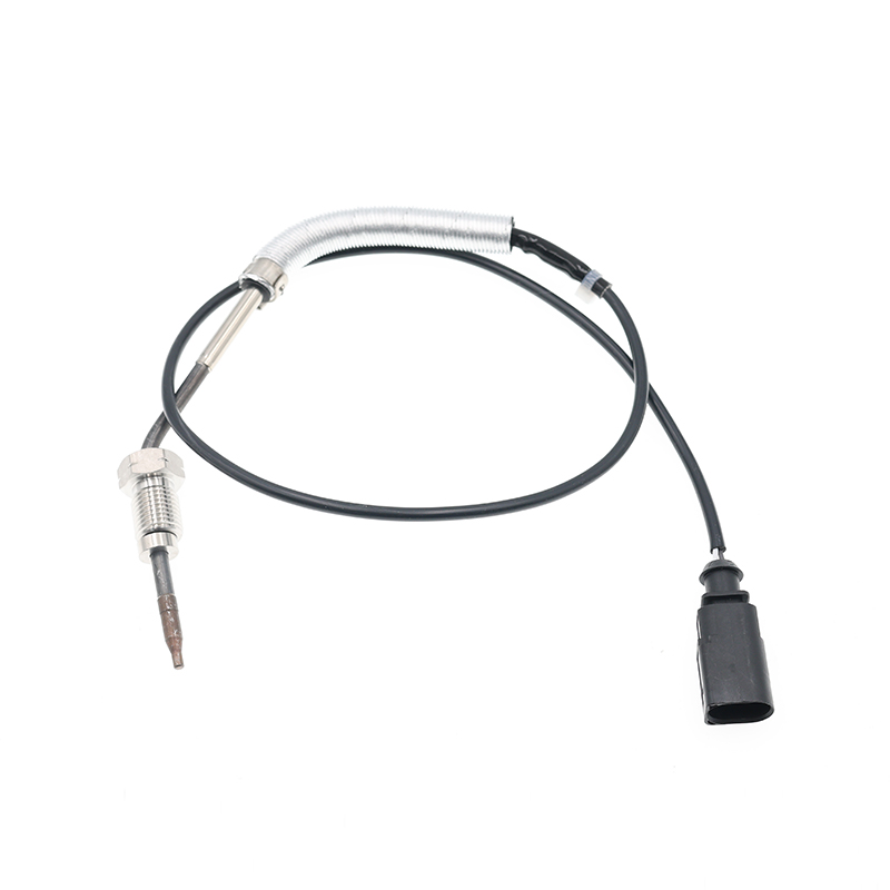
AUDIA3 (8P1) (2003/05 - 2012/08)AUDIA3 Sportback (8PA) (2004/09 - 2013/03)AUDIA4 (8EC, B7) (2004/11 ...
See Details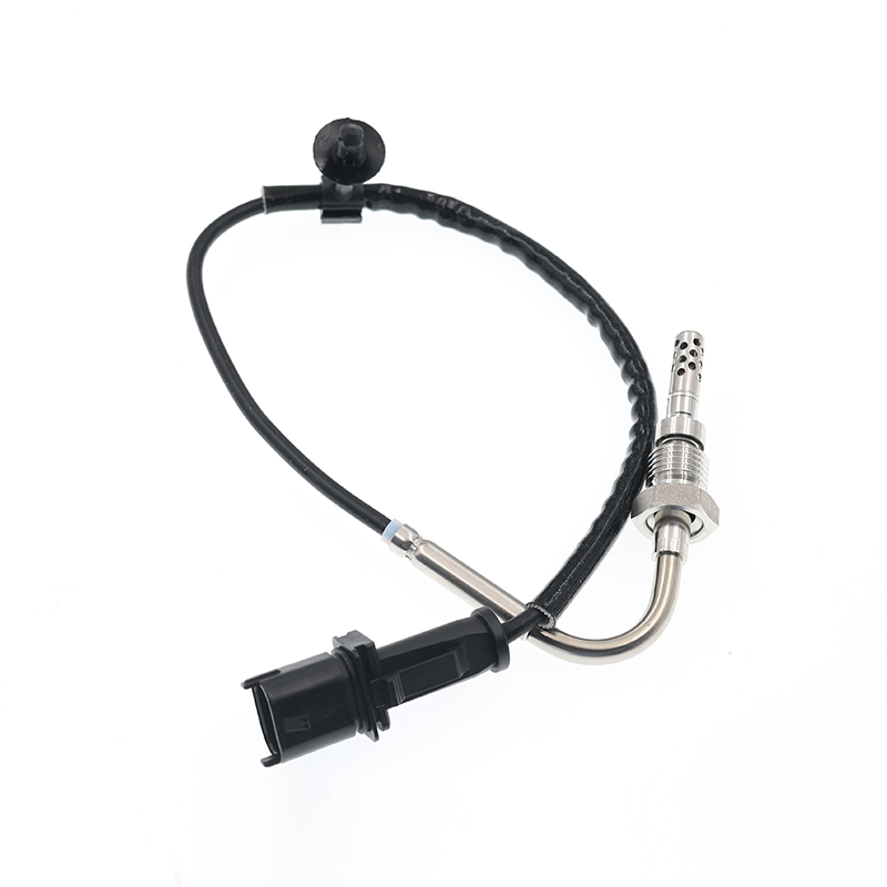
OPEL ASTRA J (2009/12 - /) OPEL ASTRA J Sports Tourer (2010/10 - /) OPEL ASTRA GTC J ...
See Details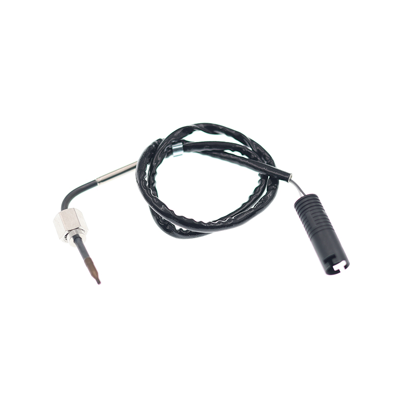
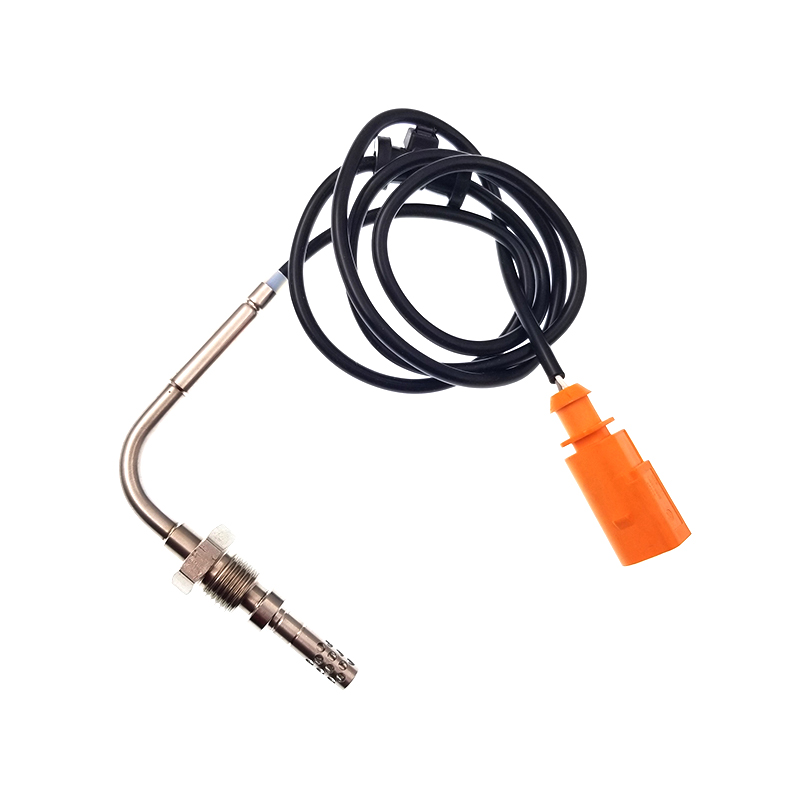
VWJETTA III (1K2) (2005/08 - 2010/10) VWGOLF VI (5K1) (2008/10 - 2013/11) VWGOLF VI Varia...
See Details
ADD: No.85 Jiuyuan Road, Economic Development Zone, Gaoyou city ,Yangzhou city ,225600 Jiangsu Province, China.
Copyright © Sook High Tech (Jiangsu) Co., Ltd. All Rights Reserved. OEM/ODM Automotive Sensor Manufacturers

