 English
 Español
 Français
 简体中文
简体中文ADD: No.85 Jiuyuan Road, Economic Development Zone, Gaoyou city ,Yangzhou city ,225600 Jiangsu Province, China.
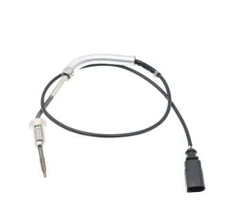
MERCEDES-BENZC-CLASS (W203) (2000/05 - 2007/08)MERCEDES-BENZC-CLASS Coupe (CL203) (2001/03 - 2011/06...
See DetailsContent
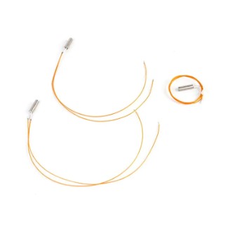
1. Sensors
A device that converts physical or chemical quantities into electrical signals is the first step in information collection.
Based on the object of perception, they can be categorized into various types, including temperature, pressure, gas, displacement, light, sound, and magnetism. They are widely used in applications such as smart cars, industrial automation, and the Internet of Things.
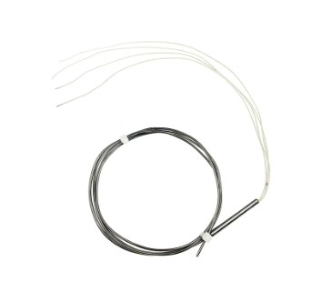
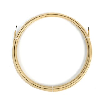
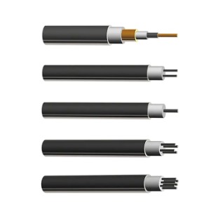
2. Industrial cables
Specialized cables used to transmit power, control signals, or data possess properties such as high temperature resistance, oil resistance, and corrosion resistance.
The structure typically consists of a conductor → insulation layer → shielding layer → sheath. Different standards (IEC, JIS, and GB) have specific requirements for voltage levels, conductor cross-sectional areas, and sheath materials.
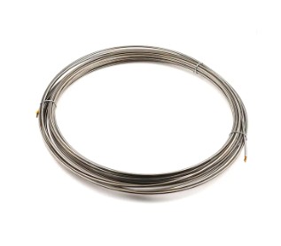
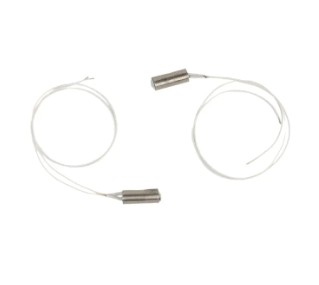
3. Heaters (industrial heaters)
Efficiently convert electrical or fuel energy into heat. Common types include resistive, inductive, and infrared. They achieve rapid heating and are energy-efficient and environmentally friendly. Depending on the heating medium, they are classified into air heaters, liquid heaters, and pipe heaters, serving a wide range of industries, including metal heat treatment, plastics processing, and food production.
| Key Parameter | Explanation | Typical Values (Examples) |
| Rated Voltage | The maximum operating voltage the cable can safely withstand. Common ratings include 0.6/1 kV, 3 kV, 6 kV, etc. | 0.6/1 kV (low‑voltage control cable) |
| Conductor Material & Cross‑Section | Copper or aluminum conductors determine current‑carrying capacity; cross‑section is expressed in mm². Larger area → lower resistance & higher current capacity. | 1.5 mm², 4 mm², 35 mm² |
| Insulation Material | Materials such as PVC, XLPE, or other polymers define temperature, oil‑resistance, and overall durability. | XLPE (high‑temperature resistance) |
| Shielding Method | Metal braid, aluminum foil, or double‑layer shielding used to suppress EMI; shielding must be grounded at both ends. | Copper braid + aluminum foil |
| Sheath Material | Outer protective layer, commonly PVC or LSZH (Low Smoke Zero Halogen), balancing flame‑retardancy and environmental safety. | LSZH (low‑smoke) |
| Construction Marking | Codes like VV, VV‑R, RVVP indicate the combination of conductor, insulation, shielding, and sheath. | RVVP‑2×1.5 mm² |
1. Voltage rating: This indicates the maximum operating voltage, such as 0.6/1kV, 3kV, or 6kV, and determines the cable's insulation thickness and material.
2. Conductor material and cross-sectional area: Copper or aluminum conductors. The cross-sectional area (mm²) determines the current-carrying capacity; commonly used specifications include 0.22mm², 1.5mm², and 35mm².
3. Sheath material: PVC, XLPE, silicone, etc., determines heat, oil, and corrosion resistance. For high-temperature applications, silicone sheaths with a resistance to temperatures above 90°C are recommended.
4. Shielding: Metal braid or aluminum foil shielding is used to suppress electromagnetic interference (EMI). The shield must be grounded at both ends.
5. Standard markings: such as XHH-W-2, RHH-W, and THHN, correspond to properties such as fire resistance, flame retardancy, and oil resistance, respectively.
1. Key points for sensor installation
The base must be flat and sufficiently rigid: The base must be smooth, free of oil, and stronger than the sensor body.
Consistent loading direction: The force line of a force sensor must coincide with the sensor axis to avoid lateral forces and torque.
Protection and corrosion resistance: The housing can be coated with petroleum jelly to prevent chemical corrosion and direct sunlight.
Grounding and shielding: All metal housings must be reliably grounded. Signal cables must use shielded twisted-pair cables and be grounded at both ends.
2. Key points for industrial cable laying
Maintain minimum spacing: The spacing between signal cables and high-power cables should be ≥30 cm. If less than this spacing, a metal separator should be used and grounded.
Bending radius: The bending radius should be no less than five times the outer diameter to prevent damage to the conductor and shield. Protective Piping: Use metal or steel sheathed conduits in mechanical impact zones to improve pressure resistance.
Marking and Layering: Cables with different functions (power, control, and signal) should be laid in separate layers to avoid cross-interference.
3. Key Points for Heater (High-Power Cable) Installation
Selecting Temperature-Resistant Cables: High-power heaters should use copper-core XLPE cables with a temperature resistance of ≥90°C and a cross-sectional area sufficient for the starting current.
Compensating for Thermal Expansion: Allow for expansion space to prevent mechanical stress caused by temperature cycling.
Shielding and Grounding: The outer sheath should be flame-retardant or LSZH, and the metal shield should be grounded at both ends to suppress EMI.
Safety Inspection: After installation, perform insulation resistance and ground continuity tests to ensure compliance with IEC 60364 standards.
1. Minimum Safety Distance:
When the distance between the signal cable and the high-power cable is less than 15cm, a metal partition must be installed between them and grounded. It is recommended to maintain a spacing of 30cm or greater to naturally reduce electromagnetic coupling.
2. Shielding Requirements:
Signal cables should be shielded with metal braid or aluminum foil. The shield should be grounded at both ends to form a complete shielding loop.
For high-frequency signals (such as RS-485 and PROFIBUS), the shield grounding resistance should be ≤0.1Ω to ensure effective shielding.
3. Crossover Routing Rules:
If crossing is unavoidable, the intersection should be at a 90° angle and metal conduit should be installed at the intersection for isolation.
Signal cables should be laid parallel to low-voltage cables as much as possible, avoiding the same rack as high-voltage cables.
4. Grounding and Wiring:
Both ends of the shield must be grounded using dedicated grounding bolts, and the grounding resistance must comply with local electrical regulations.
1. Layered Cabling Strategy
Layer 1 (High Power): Power cables for motors, heaters, and other cables ≥30kV should be installed using heat- and oil-resistant industrial cables, laid on dedicated racks.
Layer 2 (Control/Signal): Sensor signal cables should use shielded twisted-pair cables, maintaining a vertical distance of ≥30cm from the high-power layer, with metal separators installed as necessary.
Layer 3 (Communication): Fieldbus cables (such as PROFINET and EtherCAT) should use fiber optic or shielded twisted-pair cables, maintaining a 0mm distance from the power layer (on the same layer) but separated by metal to prevent EMI.
2. Unified Grounding and Shielding Management
All shields should be grounded at the distribution box to create a single-point ground to prevent ground loop noise.
The metal shield of the heater cable should also be grounded at both ends to ensure signal integrity. 3. Cable Harness and Modular Design
Prefabricated cable harnesses are used with uniform labeling and color coding for quick on-site assembly and subsequent maintenance.
Quick connectors are used at key nodes to reduce wiring errors.
4. EMC Anti-interference Measures
For high-frequency signals (such as current sensors), twisted-pair shielded cable is used, and filters are installed before the signal amplifier to improve anti-interference capabilities.
Metal partitions are placed between high-power cables and signal cables, and grounded metal pipes are installed where necessary to achieve physical isolation.
5. On-site Commissioning and Monitoring
An online monitoring system collects real-time data such as cable temperature and signal integrity to detect anomalies and perform preventive maintenance.
A thermal imager is used to check the temperature rise of heater cables to ensure they do not exceed the rated temperature.

MERCEDES-BENZC-CLASS (W203) (2000/05 - 2007/08)MERCEDES-BENZC-CLASS Coupe (CL203) (2001/03 - 2011/06...
See Details


AUDIQ7 (4L) (2006/03 - 2015/08)VWTOUAREG (7LA, 7L6, 7L7) (2002/10 - 2010/05)
See Details
AUDIA3 (8P1) (2003/05 - 2012/08)AUDIA3 Sportback (8PA) (2004/09 - 2013/03)AUDIA4 (8EC, B7) (2004/11 ...
See Details
OPEL ASTRA J (2009/12 - /) OPEL ASTRA J Sports Tourer (2010/10 - /) OPEL ASTRA GTC J ...
See Details

VWJETTA III (1K2) (2005/08 - 2010/10) VWGOLF VI (5K1) (2008/10 - 2013/11) VWGOLF VI Varia...
See DetailsADD: No.85 Jiuyuan Road, Economic Development Zone, Gaoyou city ,Yangzhou city ,225600 Jiangsu Province, China.
Copyright © Sook High Tech (Jiangsu) Co., Ltd. All Rights Reserved. OEM/ODM Automotive Sensor Manufacturers

