 English
 Español
 Français
 简体中文
简体中文ADD: No.85 Jiuyuan Road, Economic Development Zone, Gaoyou city ,Yangzhou city ,225600 Jiangsu Province, China.
MERCEDES-BENZC-CLASS (W203) (2000/05 - 2007/08)MERCEDES-BENZC-CLASS Coupe (CL203) (2001/03 - 2011/06...
See DetailsContent
1. Concept Explanation
Automotive sensors are devices that convert physical or chemical quantities such as temperature, pressure, displacement, flow, and chemical composition in parts of the engine, chassis, and body into voltage, current, or digital signals.
These signals are then collected and analyzed in real time by the vehicle's electronic control unit (ECU) for closed-loop control, ensuring the precise operation of systems such as engine fuel injection, ignition timing, emissions control, and anti-lock braking systems.
2. Main Categories
Temperature sensors (thermocouples, RTDs, infrared): Monitor coolant, oil, and exhaust temperatures.
Pressure sensors (piezoelectric, piezoresistive): Measure fuel, intake air, oil pressure, and brake oil pressure.
Position/speed sensors (Hall, magnetoresistive, photoelectric): Detect crankshaft, camshaft, wheel speed, steering angle, and more.
Chemical sensors (oxygen, NOx, NH₃, H₂): Monitor exhaust gas composition, helping aftertreatment systems achieve low emissions.
3. Technical Features
High precision: Errors are generally controlled within ±1% to ±2%. Wide Temperature Range: Exhaust gas temperature sensors, in particular, must maintain linearity in extreme environments ranging from 200°C to 800°C.
Interference Prevention: Shielded cables, differential signals, or digital buses (CAN, LIN) are used to reduce the impact of electromagnetic noise.
4. SOOKHighTech's Competitive Advantages
R&D Strength: The company holds National High-Tech Enterprise status, and its R&D team covers three core areas: sensor materials, microelectronics packaging, and signal processing.
Production Capacity: Annual production capacity of 600,000 sensors of various types. The product line includes over 2,600 exhaust gas temperature sensors, over 450 NOx sensors, and over 1,300 ABS sensors, meeting high-volume OEM/ODM needs.
International Certifications: Our products have passed ISO/TS 16949, IATF 16949, CE, UL, and other certifications, and are popular in the European and American markets. They meet stringent emission standards such as Euro VI and the US EPA.
1. Real-Time Data Acquisition and Closed-Loop Control
Real-time operating data provided by sensors serves as input for key ECU algorithms such as fuel injection, ignition advance, turbocharging, and exhaust aftertreatment.
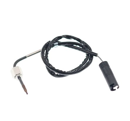
For example, the exhaust gas temperature sensor (EGTS) monitors the temperatures before and after the catalytic converter, helping the ECU dynamically adjust the EGR (exhaust gas recirculation) valve opening to reduce nitrogen oxide emissions.
2. Safety and Active Function Support
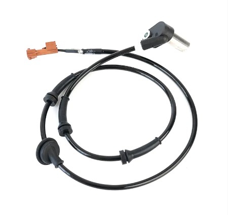
ABS/ESP: Wheel speed sensors provide information about the rotational speed of each wheel, and the ECU implements anti-lock braking and electronic stability control by comparing differential speeds.
Airbag System: Accelerometers detect collision impact intensity, triggering rapid airbag deployment.
Autonomous Driving: The integration of LiDAR, cameras, and ultrasonic sensors provides the foundation for path planning and obstacle detection.
3. Fault Diagnosis and Convenient Maintenance
The OBD-II standard stipulates that each key sensor anomaly must be associated with a unique fault code (DTC), allowing maintenance personnel to quickly locate the problem using a diagnostic tool. Sensor self-test functions (such as cold start self-test and heating element self-test) further enhance timely fault detection.
4. SOOK HighTech's System Compatibility
Our sensors utilize a CAN FD and LIN dual-bus compatible design at the hardware level, enabling seamless integration into the electronic architectures of major domestic and international automakers.
SOOK HighTech also participates in the development of industry standards with organizations such as the China Machinery Industry Standardization Association and the Sensor and Internet of Things Industry Alliance to ensure product consistency and reliability across the entire vehicle system.
1. Electrical Failure
Open/Short Circuit: Loose solder joints and worn wiring lead to signal interruption or short circuit, often manifesting as a solid malfunction light or ECU error.
Increased Contact Resistance: Oxidation or loosening of connectors increases signal noise, leading to measurement drift.
2. Aging of Sensing Components
Thermocouple/RTD Drift: Long-term high-temperature cycling changes material properties, resulting in a decrease in the linearity of output voltage/resistance with temperature.
Magnetic Saturation of Optoelectronic/Magnetic Components: Loss of sensitivity in strong magnetic fields or high-temperature environments.
3. Mechanical Damage
Vibration and Shock: High-frequency vibrations within the engine compartment can cause cracks in the sensor housing and loosen the internal chip.
Improper Installation: If the EGTS mounting bolts are not tightened or the thermal expansion coefficients are mismatched, an abnormal temperature difference between the hot and cold ends will occur.
4. Environmental Corrosion
Salt Spray and Humidity: Metal pins are susceptible to corrosion, especially on coastal areas or on salted roads in winter, leading to signal distortion.
Chemical Attack: Sulfides, ammonia, and other gases in the exhaust system can corrode the sensor packaging material.
5. SOOKHighTech's Failure Prevention Measures
Material Selection: High-temperature, corrosion-resistant stainless steel and ceramic packaging are used to enhance oxidation and salt spray resistance.
Structural Design: Anti-vibration mounts and thread locking devices are added to ensure stability even in vibration environments exceeding 30g.
Reliability Testing: Four accelerated aging tests—temperature shock, salt spray, vibration, and thermal cycling—are performed to ensure trouble-free operation for over 100,000 kilometers.
1. Core Principle
Thermocouple-type EGTS: Two dissimilar metals (such as platinum and rhodium) generate a small thermoelectric potential at their junction, which is linearly proportional to temperature (approximately 40µV/°C).
Resistor-type EGTS (RTD): A platinum resistor is used, whose resistance is proportional to temperature (approximately 0.385Ω/°C). This is converted to a voltage signal via a bridge circuit.
2. Signal Processing Chain
Front-end Amplification: The low-voltage signal is amplified by a differential amplifier to suppress common-mode noise.
Linearization Calibration: The ECU uses a built-in lookup table or polynomial algorithm to map the raw voltage to the actual temperature value.
Fault Self-Detection: If the signal exceeds a preset range (e.g., 0V–5V), the system automatically flags it as a "sensor failure."
3. Installation Location and Thermal Management
Typical Placement: EGTS are commonly installed in the exhaust manifold, before and after the turbine, and before the catalytic converter to capture temperature information at different stages. Thermal Protection: The sensor housing is constructed of a double-layer stainless steel tube filled with high-temperature ceramic fiber to prevent metal fatigue caused by thermal shock.
4. SOOKHighTech Technical Highlights
Wide Temperature Range: The product covers a temperature range of 200°C–800°C, meeting the full range of requirements from low-speed urban driving to high-power sports engines.
Fast Response: The thermocouple chip has a response time of < 10ms, ensuring that the ECU can instantly adjust to transient load changes.
Anti-Interference Design: Shielded twisted-pair cable + differential signal transmission maintains signal integrity even in high-noise environments.
| Step | Operation Details | Common Indicators |
| Connect the diagnostic tool | Plug the OBD‑II scanner into the 16‑pin connector. | The scanner’s indicator light stays on, confirming successful communication. |
| Turn the ignition to ON (engine does not need to start). | ||
| Enter the exhaust system diagnostic menu | In the scanner’s menu select Engine → Exhaust Gas Temperature Sensor (EGTS). | Under normal conditions, a cold start shows ~200 °C, which rises steadily as the engine warms up. |
| Read the real‑time voltage/temperature values. | ||
| Retrieve fault codes (DTCs) | Choose Read Fault Codes. | If a U0100 (communication fault) appears, first inspect the wiring harness. |
| Note any codes returned, e.g., P2200 (EGTS circuit fault) or P2195 (EGTS failure). | ||
| View snapshot/history data | Access Snapshot/History to see the temperature, throttle position, engine speed, etc., at the moment the fault was triggered. | Compare the snapshot temperature with the values specified in the service manual to determine whether the issue lies in the sensor itself or in external wiring. |
| Perform on‑site visual inspection | Visually check the EGTS connector for corrosion or looseness. | If resistance/voltage is out of range, replace the sensor with an original‑equipment SOOK High Tech EGTS and re‑calibrate. |
| Use a multimeter to measure the sensor’s resistance or voltage and verify it falls within specification. | ||
| Clear fault and verify | Clear the fault codes, then restart the engine and monitor for 5–10 minutes. | If the lamp re‑lights, further investigation of the ECU power supply or CAN‑bus integrity is required. |
| If the warning lamp does not illuminate again, the problem is resolved. |
1. Connecting the diagnostic tester
Plug the diagnostic tester's OBD-II interface into the 16-pin diagnostic socket below the vehicle's dashboard.
Turn the ignition key to ON. The diagnostic tester will automatically identify the vehicle model and establish ECU communication.
2. Enter Exhaust System Diagnostic Mode
In the diagnostic tester menu, select Engine System → Exhaust Gas Temperature Sensor (EGTS). Read the current sensor voltage or temperature. If the value is abnormal (such as a persistently low voltage or a temperature reading that doesn't change with engine load), it indicates a potential fault.
3. Read DTCs
Select Read DTCs (DTCs). The system will return a code such as P2200 (EGTS circuit fault) or P2195 (EGTS sensor failure).
You can further view the Snapshot or Extended Information to obtain detailed parameters such as the instantaneous temperature and voltage at the time of the fault.
Step 4: Confirm and Address
Compare the real-time temperature reading with the normal range specified in the service manual. If there is a significant deviation and the DTC corresponds to EGTS, there is a problem with the sensor itself or the wiring.
Based on the company's high-temperature and vibration-resistant design, it is recommended to replace the EGTS with a genuine SOOK HighTech EGTS and inspect the terminal anti-corrosion treatment.

MERCEDES-BENZC-CLASS (W203) (2000/05 - 2007/08)MERCEDES-BENZC-CLASS Coupe (CL203) (2001/03 - 2011/06...
See Details


AUDIQ7 (4L) (2006/03 - 2015/08)VWTOUAREG (7LA, 7L6, 7L7) (2002/10 - 2010/05)
See Details
AUDIA3 (8P1) (2003/05 - 2012/08)AUDIA3 Sportback (8PA) (2004/09 - 2013/03)AUDIA4 (8EC, B7) (2004/11 ...
See Details
OPEL ASTRA J (2009/12 - /) OPEL ASTRA J Sports Tourer (2010/10 - /) OPEL ASTRA GTC J ...
See Details

VWJETTA III (1K2) (2005/08 - 2010/10) VWGOLF VI (5K1) (2008/10 - 2013/11) VWGOLF VI Varia...
See DetailsADD: No.85 Jiuyuan Road, Economic Development Zone, Gaoyou city ,Yangzhou city ,225600 Jiangsu Province, China.
Copyright © Sook High Tech (Jiangsu) Co., Ltd. All Rights Reserved. OEM/ODM Automotive Sensor Manufacturers

